Device at fixing means for fixation of bone fragments at bone fractures

a technology for fixing means and bone fragments, applied in the field of devices for fixing means for fixing bone fragments at bone fractures, can solve the problems of pin not finding its way out, deformation inside, pin unintentionally moving or being moved from a ready position, etc., and achieves the effect of stable fixation of bone fragments and reduced likelihood of pin penetration

Inactive Publication Date: 2006-04-18
HANSSON HENRIK
View PDF18 Cites 24 Cited by
  • Summary
  • Abstract
  • Description
  • Claims
  • Application Information

AI Technical Summary

Benefits of technology

[0005]By providing the device with said characterizing features, the pin is prevented from unintentional movement out of a ready position and / or is it ensured that the end portion of the pin gets an advantageous curvature such that a stable fixation of the bone fragment is obtained and the likelihood that said pin penetrates the bone fragment is reduced.

Problems solved by technology

There is however, always a risk that the pin does not find its way out through the side opening, but is deformed inside the sleeve if it occupies or is brought to occupy an erroneous position in relation thereto.
This may be due to that the pin unintentionally moves or is moved from a ready position, e.g. by being turned or rotated relative to the sleeve through the influence from rotatable members of a driving or actuator instrument.
There is also a risk that those parts of the front end portion of the pin which are driven into surrounding bone material are not deformed into an advantageous curvature.
This results in that there is a risk that the fixing means does not get the intended function, namely stable fixation of the bone fragments relative to each other.
There is also a risk that the front end portion of the pin due to a faulty design penetrates the bone fragment it is forced into.

Method used


Image

  • Device at fixing means for fixation of bone fragments at bone fractures
  • Device at fixing means for fixation of bone fragments at bone fractures
  • Device at fixing means for fixation of bone fragments at bone fractures

Examples


Embodiment Construction

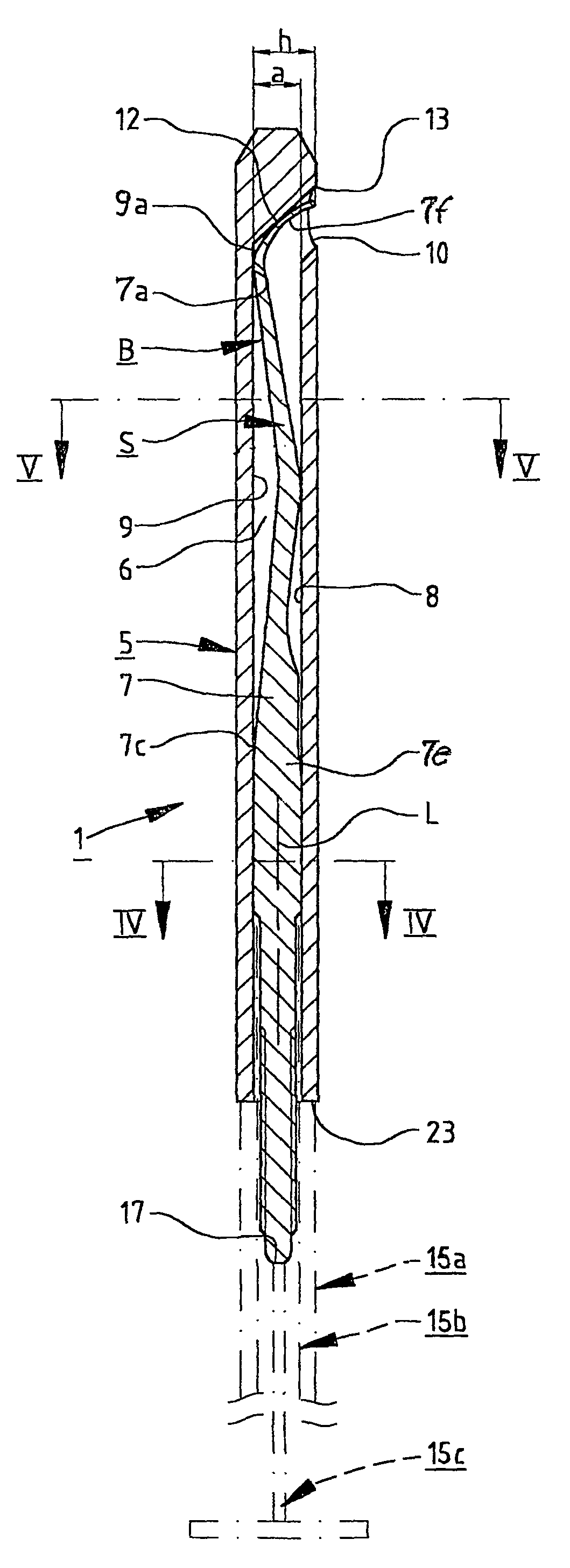
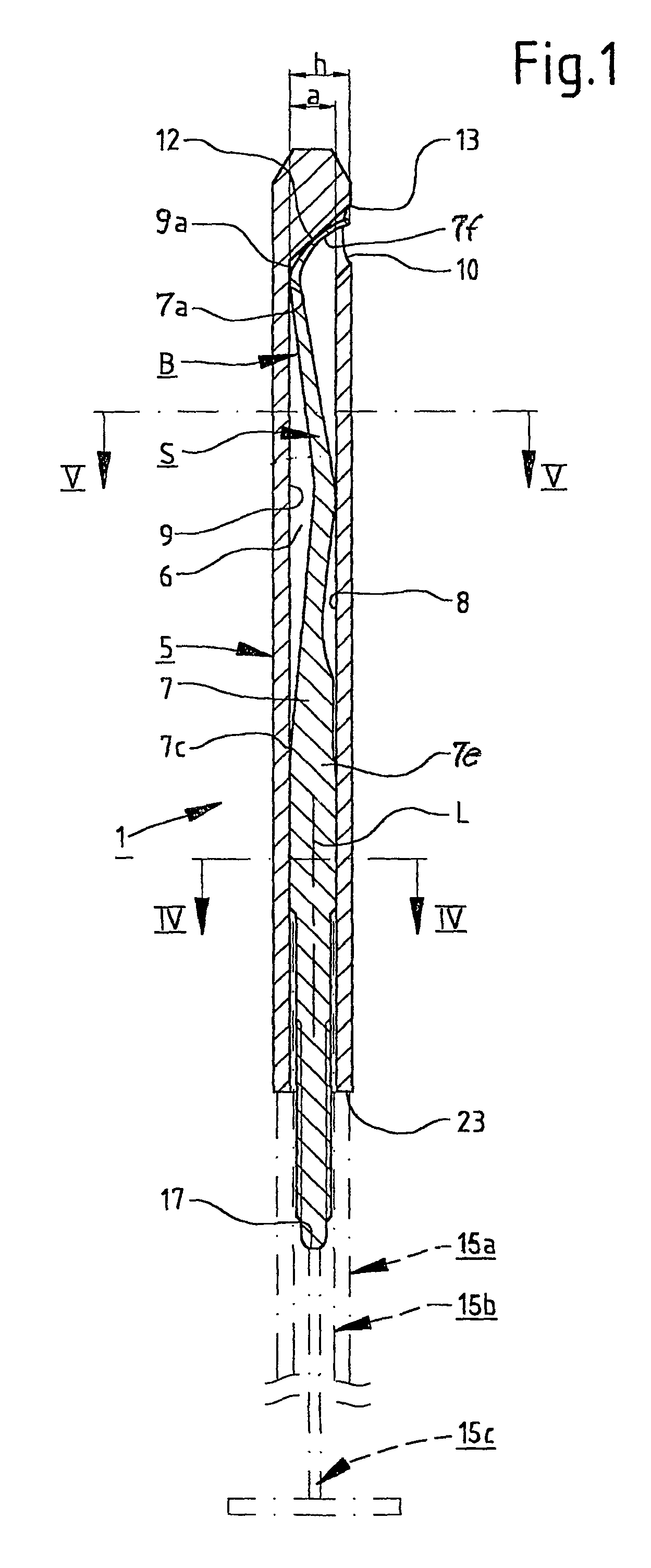
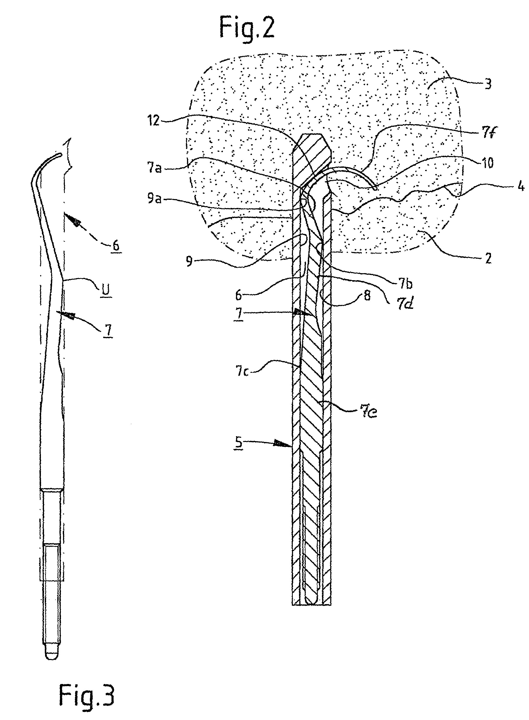
[0013]The fixing means 1 illustrated in the drawings is adapted for fixation of bone fragments at bone fractures. Preferably, the fixing means 1 is a spike for thigh-bone necks, a collum spike, for fixation of bone fragments 2, 3 at fractures 4 of the thighbone neck.

[0014]The spike 1 comprises a sleeve 5 with an elongated space 6 which is open at the rear for insertion of a pin 7. The elongated space 6 has a circular or substantially circular cross section.

[0015]The sleeve 5 has a first longitudinal wall surface 8 and opposite thereto, a second longitudinal wall surface 9. In the first longitudinal wall surface 8 there is provided a side opening 10 and from a front edge 13 of said side opening 10, a guide surface 12 protrudes in a backwards inclined direction to the second longitudinal wall surface 9.

[0016]The pin 7 has a front end portion 7f which preferably is curved. This front end portion 7f is adapted to be guided by the guide surface 12 such that it is forced out of the space ...


PUM


Abstract

The present invention relates to a device at fixing means for fixation of bone fragments at bone fractures, wherein the fixing means (1) preferably is a spike for thigh-bone necks for fixation of bone fragments (2.3) at fractures (4) of the thigh-bone neck. The fixing means (1) comprises a sleeve (5) and a pin (7) provided therein. The pin (7) includes a front part (7a) which is directed obliquely forward relative to a rear part (7e) thereof and towards front parts (9a) of a second wall surface (9) close to a guide surface (12) of the sleeve (5) when the pin (7) is located in a ready position (B) in said sleeve (5).

Description

FIELD OF THE INVENTION[0001]The present invention relates to a device at fixing means for fixation of bone fragments at bone fractures, wherein the fixing means preferably is a spike for thigh-bone necks for fixation of bone fragments at fractures of the thigh-bone neck, wherein the fixing means comprises a sleeve which is open at the rear for insertion of a pin into a ready position, wherein the sleeve defines an elongated space with two opposite wall surfaces, namely a first longitudinal wall surface in which there is provided a side opening and a longitudinal second wall surface from which a guide surface extends in an inclined forward direction to a front edge of the side opening, and wherein the guide surface is provided to guide a front, preferably curved end portion of the pin to force its way out through the side opening when said pin is displaced in a forward direction relative to the sleeve.BACKGROUND OF THE INVENTION[0002]Fixing means of the abovementioned type are known ...

Claims


Application Information

Patent Timeline
Patent Type & Authority Patents(United States)
IPC IPC(8): A61B17/56A61F2/30A61B17/58A61B17/34A61B17/68A61B17/72A61B17/74
CPCA61B17/68A61B17/7266Y10S606/907A61B2017/3488A61B17/74
Inventor HANSSON, HENRIK
Owner HANSSON HENRIK
Why Eureka
Try Eureka