Power supply unit

Inactive Publication Date: 2006-04-18
HONDA MOTOR CO LTD
View PDF6 Cites 38 Cited by
  • Summary
  • Abstract
  • Description
  • Claims
  • Application Information

AI Technical Summary

Benefits of technology

[0009]It is an object of the present invention to provide a low-cost and light-weight battery-type power supply unit of the above-mentioned type that can prevent breakage of the connection between positive and negative electrode

Problems solved by technology

However, in the conventional system, since each battery module is supported by substantially its opposite ends, vibration causes a large amplitude of oscillation of each battery module, leading to a possibility that it might break the connection between the positive and negative electrodes of two adjacent batteries.
Furthermore, since the bus-bars are fixedly embedded in the end plates, any variation in the axial dimension of the battery modules cannot easily be accommodated.
Moreover, since the synthetic re

Method used


Image

  • Power supply unit
  • Power supply unit
  • Power supply unit

Examples


Example

[Embodiment I]

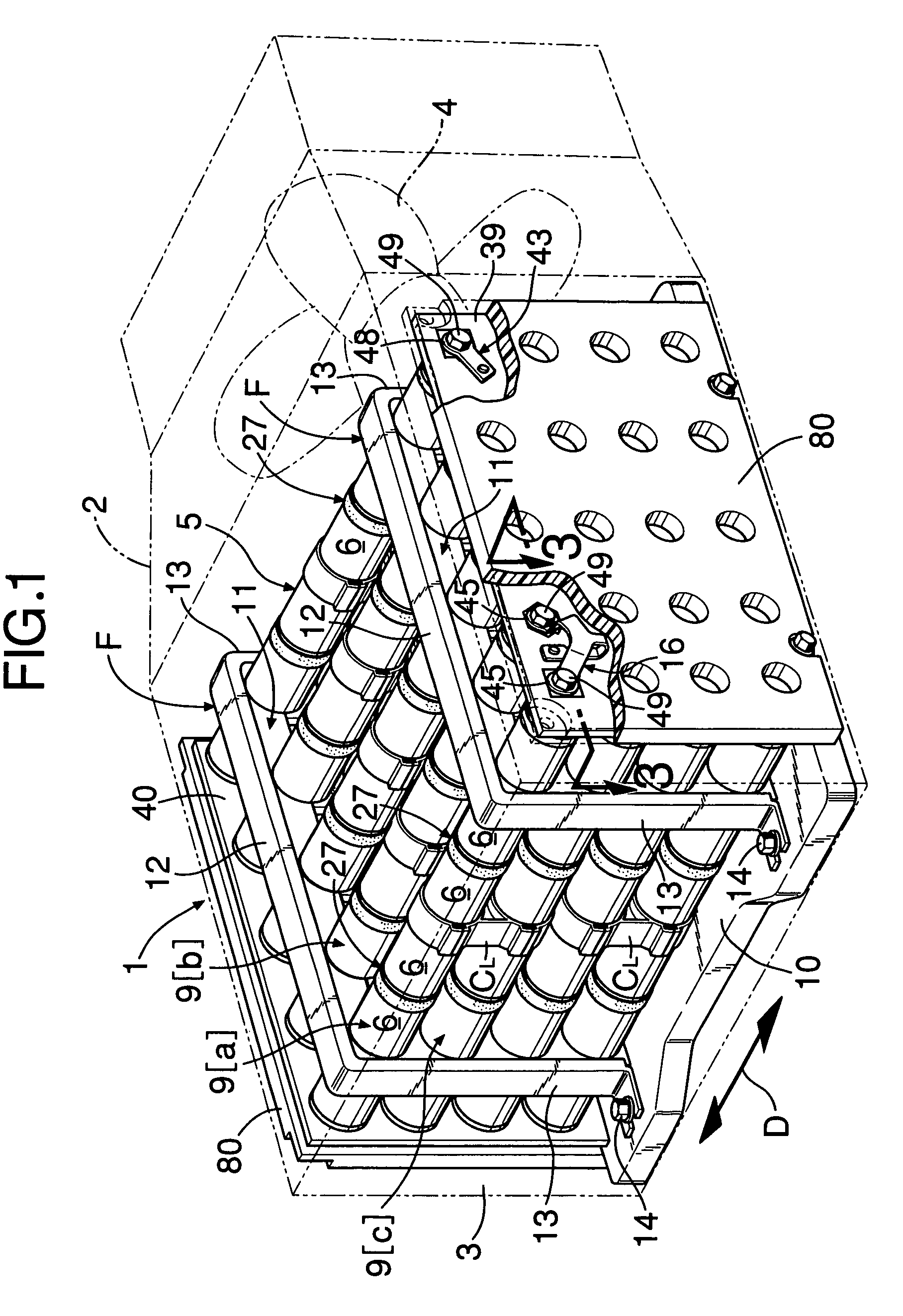
[0050]Referring to FIGS. 1 and 2, a battery-type power supply unit 1 includes a thin synthetic resin box 2. The box 2 has a cooling air inlet 3 in a face at one end and a suction fan 4 within a section at the other end. A battery assembly 5 is housed within the box 2 between the cooling air inlet 3 and the suction fan 4, that is, in a middle section within the box 2.

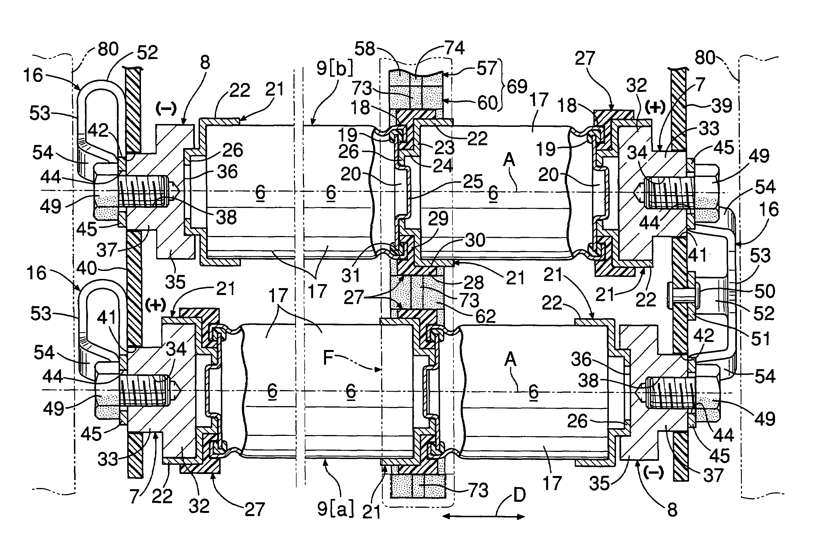
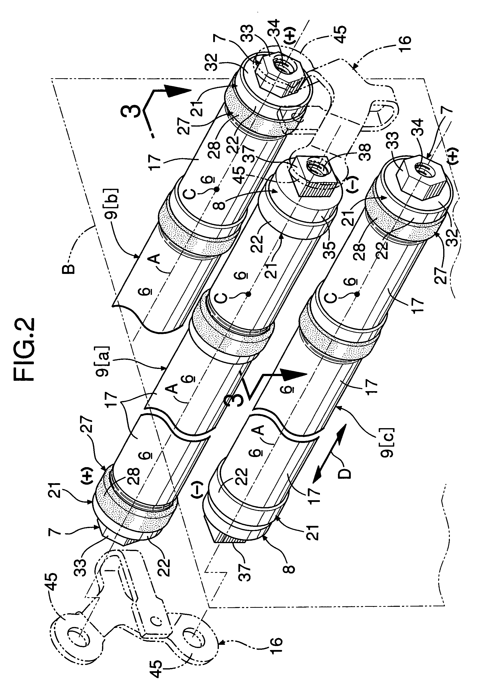
[0051]The battery assembly 5 includes a plurality, 20 in the embodiment, of rod-shaped battery modules 9 that are each formed from a plurality, six in the embodiment, of batteries 6 connected together in series, and each has a positive electrode 7 at one end and a negative electrode 8 at the other end. These battery modules 9 are arranged so that axes A thereof are parallel to each other and, on an imaginary plane B intersecting these axes A. There are four points of intersection C of the axes A and the imaginary plane B in the vertical direction and five in the lateral direction. Positive / negative electrod...

Example

[Embodiment II]

[0072]In FIGS. 17 and 18, a battery-type power supply unit 1 includes a substantially rectangular parallelepiped box 2 and a battery assembly 5 disposed within the box 2. The box 2 is formed from a steel base 90 and a synthetic resin (or metal) cover 91. The base 90 is formed from a support plate 92 and a shielding plate 93 rising from one edge of the support plate 92 and facing one side of the battery assembly 5. The battery assembly 5 is in the form of a substantially rectangular parallelepiped block and is placed on the support plate 92. The support plate 92 has two ridges 94 disposed at an interval, and each ridge 94 is formed orthogonal to the shielding plate 93 and has a flat top face 95. The height of each ridge 94 is smallest on the shielding plate 93 side and gradually increases with distance from the shielding plate 93. The base 90 is disposed such that the top face 95 of each ridge 94 is horizontal.

[0073]As also shown in FIG. 19, three sides of the battery ...


PUM


Abstract

A battery-type power supply unit includes a plurality of rod-shaped battery modules having a plurality of batteries connected together in series. Held tightly between two opposing ends of two batteries is an insulating ring having annular recesses into which these two ends can fit. Each battery module runs through and is supported by two plate-shaped members that are kept vertical on a base plate by frame members. Each plate-shaped member is an assembly of a plurality of grommets formed from two split halves. Connections between bus-bars and positive and negative electrodes of the battery modules can move toward and away from the positive and negative electrodes.

Description

BACKGROUND OF THE INVENTION[0001]1. Field of the Invention[0002]The present invention relates to a battery-type power supply unit, and in particular to a power supply system that includes a battery assembly in which a plurality of rod-shaped battery modules are arranged so that the axes thereof are parallel to each other and, in an imaginary plane intersecting these axes, points of intersection of the axes and the imaginary plane are aligned in both the vertical direction and the lateral direction, the rod-shaped battery modules having a plurality of batteries that are connected together in series.[0003]This type of battery-type power supply unit is mounted on a battery car, a hybrid car, a fuel cell vehicle, etc. and used as a power source. The battery concept referred to here includes those having various types of storage function such as a large capacity electric double-layer capacitor as well as a primary battery and a secondary battery.[0004]2. Description of the Related Art[00...

Claims


Application Information

Patent Timeline
IPC IPC(8): H01M6/42H01R24/00H01M10/50H01M50/213H01M50/505H01M50/51H01M50/517H01M50/522
CPCH01M2/1077H01M2/204H01M2/26H01M10/5073H01M10/503H01M10/5057H01M10/5067H01M10/5004H01M6/42H01M10/5016H01M10/625H01M10/6563H01M10/6556H01M10/643H01M10/6566H01M10/613Y02E60/10H01M50/522H01M50/213H01M50/517H01M50/51H01M50/505
Inventor BANDO, MASASHINAGANUMA, ATSUHIROOYA, SATOYOSHISHIBUYA, KENTARO
Owner HONDA MOTOR CO LTD
Why Eureka
Try Eureka