Security system and moving robot

a technology of security system and moving robot, which is applied in the field of security system, can solve the problems of inability to accept widespread solutions, inability to reach the scene in time, and the problem of too many false alarms in existing home security systems, and achieve the effect of simplifying security systems

Inactive Publication Date: 2006-04-18
KK TOSHIBA
View PDF11 Cites 150 Cited by
  • Summary
  • Abstract
  • Description
  • Claims
  • Application Information

AI Technical Summary

Problems solved by technology

However, existing home security systems suffer from too many false alarms caused by oversensitive sensors, for example, and security guards must be dispatched to the scene of the alarm for each incident.
However, it takes time for security guards to reach the scene and ascertain the situation.
However, because of privacy issues, this solution cannot be widely accepted.
Moreover, it is not practical to install security cameras or other sensors in all rooms or spaces of a house.

Method used


Image

  • Security system and moving robot
  • Security system and moving robot
  • Security system and moving robot

Examples


first embodiment

[0028]First explained is a basic configuration of a security system according to the invention.

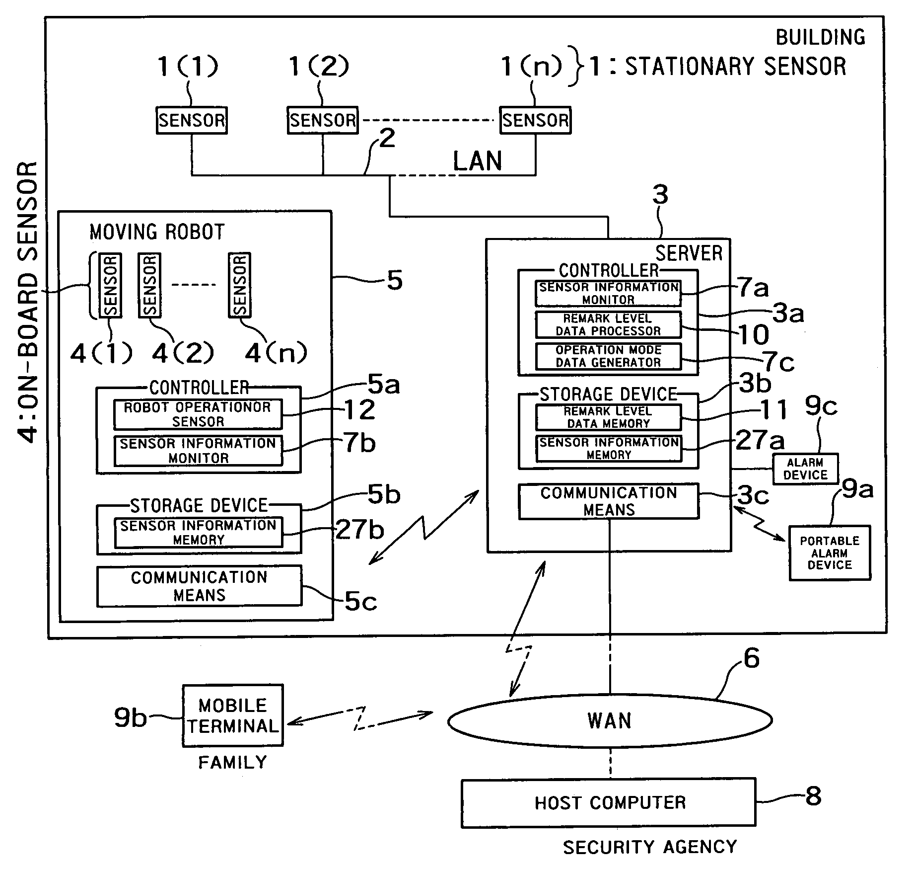
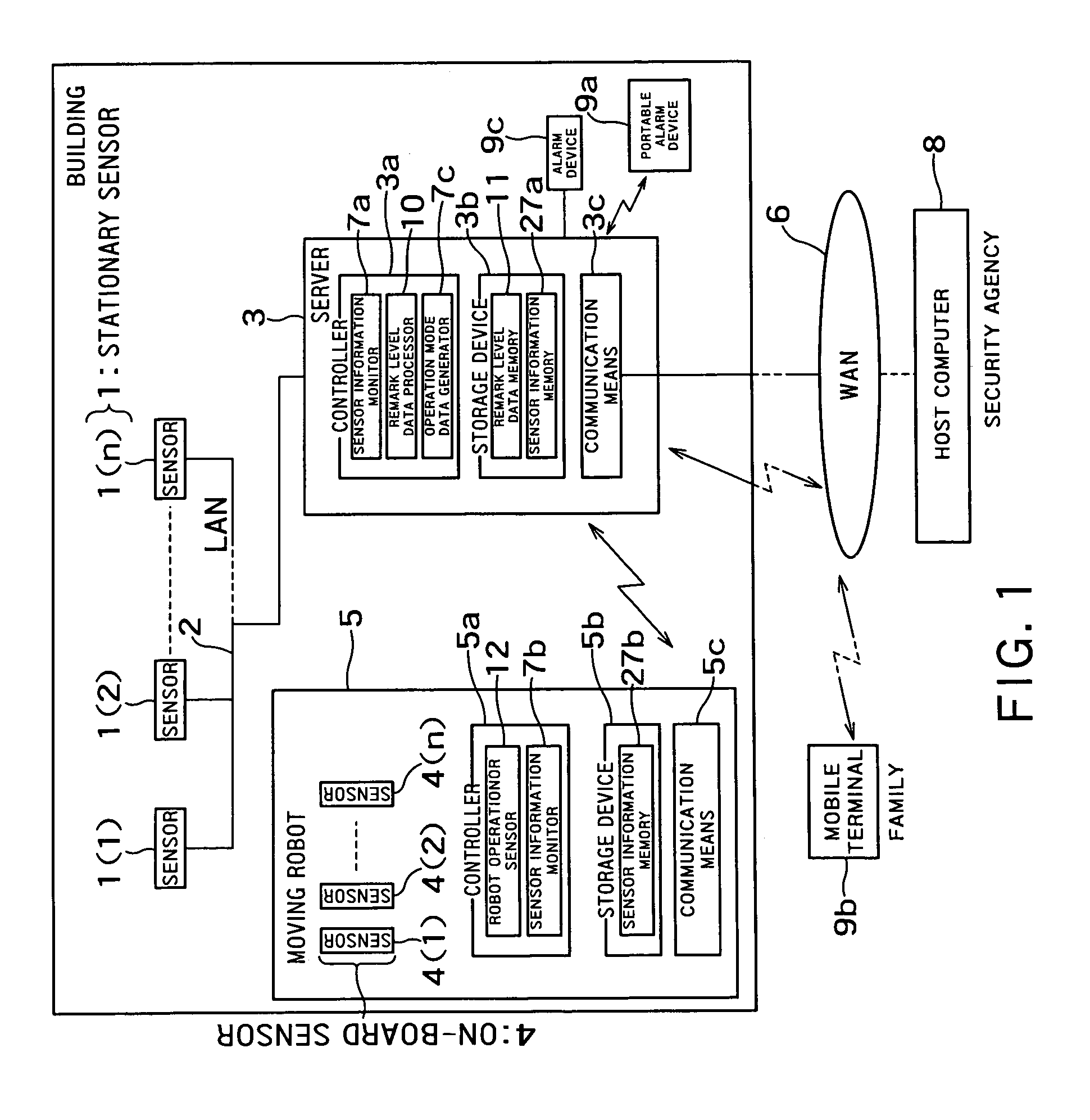
[0029]FIG. 1 is a block diagram showing the entire configuration of a security system according to an embodiment of the invention.

[0030]Stationary security sensors 1(1), 1(2), . . . 1(n) are installed on windows, entrances, etc. of a certain kind of facility or of a private residence, for example. The stationary sensors 1 may be image sensors (video cameras), vibration sensors, acoustic sensors (microphones), infrared sensors, ultrasonic wave sensors, or the like, for example.

[0031]Stationary sensors 1 installed in such a building are connected to a communicator 3c of a home server (or a server) 3 for controlling various devices in the building through a network (such as a local area network (LAN)) 2 installed in the building. The home server 3 includes a sensor information monitor 7a. The sensor information monitor 7a receives (collects) detection data (sensor information) from the statio...

second embodiment

[0067](Second Embodiment): Monitoring System 2 using Remark Level Data

[0068]FIG. 7 is a diagram showing a layout of a home security system taken as the second embodiment, which is installed in a residence.

[0069]As shown in FIG. 7, this security system does not equip noticeable windows and entrance with stationary sensors but selectively equips only unnoticeable windows (ex. windows of Living room 26, Lav 28 bath room 29 and bed room 31) with stationary sensors. The moving robots 5(1), 5(2) provided on the first-floor and the second floor detect intruder from the windows, etc. not equipped with stationary sensors.

[0070]This security system does not equip noticeable windows and entrance with stationary sensors but selectively equips only unnoticeable windows with stationary sensors. Therefore, this security system can use stationary sensors and moving robots in a more effective cooperative manner. That is, the windows, etc. equipped with stationary sensors are monitored by the station...

third embodiment

[0073](Third Embodiment): Method of Changing Remark Level Data

[0074]In this embodiment, remark level data once determined for stationary sensors, rooms, spaces, persons, etc. are dynamically changed on the basis of sensor information detected by stationary sensors and on-board sensors. Thus, the embodiment attains more flexible monitoring.

[0075]In the first and second embodiments, the moving robot 5 is equipped with the remark level processor 10, remark level data memory 11, and operation mode data generator 7c. In this and subsequent embodiments, the home security servers 3 includes those components.

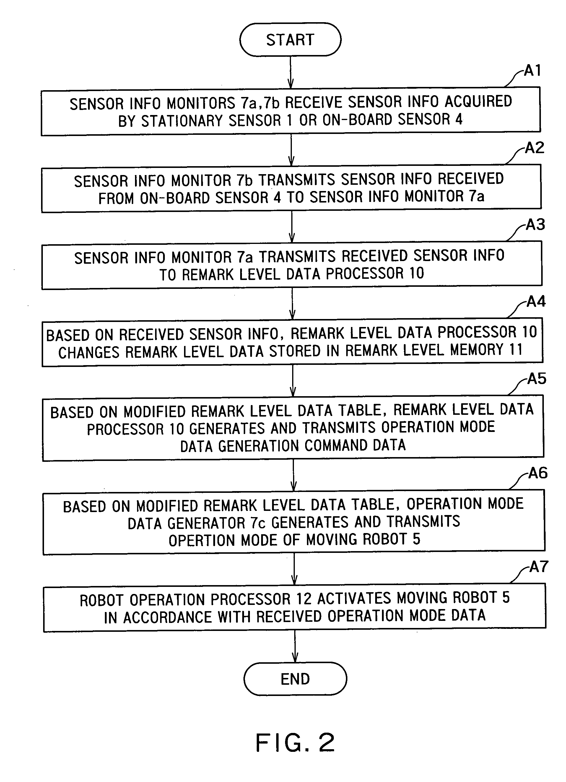
[0076]FIG. 9 is a flowchart of procedures for dynamically modifying remark level data once determined for the stationary sensors 1 in accordance with sensor information detected by the stationary sensors 1, etc. themselves.

[0077]As its example, FIG. 9 shows remark level data modification (B1) based on data indicating frequencies of abnormality detection by the stationary sensors (abnorm...


PUM


Abstract

A security system comprises a first sensor disposed in an area to be monitored in a building to monitor the area; a moving robot having a robot main body, a second sensor for monitoring the area to be monitored and a robot operation processor for moving the robot main body according to an operation mode data indicating an operation of the robot main body; a controller including first and second sensor information monitor units for collecting first sensor information and second sensor information which are acquired by the first and second sensors, and an operation mode data generator for generating the operation mode data from the first sensor information or the second sensor information and transmitting the operation mode data to the robot operation processor.

Description

CROSS-REFERENCE TO RELATED APPLICATIONS[0001]This application is based upon and claims the benefit of priority from the prior Japanese Patent Application No. 2002-348059, filed on Nov. 29, 2002, the entire contents of which are incorporated herein by reference.BACKGROUND OF THE INVENTION[0002]1. Field of the Invention[0003]This invention relates to a security system and more particularly to a security system using a moving robot.[0004]2. Related Background Art[0005]Lock picking is a more common means of illegal entry among burglars these days, and this has raised the need for better security against lock picking. Accordingly, security systems formerly intended for commercial buildings and luxury residences have spread to ordinary apartments and houses as well. Home security systems use security cameras, sensors to detect the movements of doors or windows, human motion sensors, vibration sensors for detecting breakage of windowpanes, and the like, which are installed within the resid...

Claims


Application Information

Patent Timeline
Patent Type & Authority Patents(United States)
IPC IPC(8): G08B13/00B25J5/00B25J13/00G08B13/196G08B25/00G08B25/04
CPCG08B13/19645G08B13/19647G08B29/188G08B13/19697G08B13/19684G05D1/0274G05D2201/0209
Inventor MATSUHIRA, NOBUTOTAKAHARA, KENICHI
Owner KK TOSHIBA
Why Eureka
Try Eureka