Supercharge Your Innovation With Domain-Expert AI Agents!

DC-to-DC converter with improved transient response

a transient response and converter technology, applied in the field of voltage converters, can solve the problems of non-fixed frequency, slow response to load transients, etc., and achieve the effect of reducing recovery time and minimizing output voltage rippl

Inactive Publication Date: 2006-04-18
O2 MICRO INT LTD
View PDF34 Cites 21 Cited by
  • Summary
  • Abstract
  • Description
  • Claims
  • Application Information

AI Technical Summary

Benefits of technology

The solution achieves very fast response to load transients, reduced output voltage ripple, and stable output voltage with minimal duty cycle variation, even under heavy loads, with recovery times as low as 10 μs and improved efficiency in multiphase configurations.

Problems solved by technology

Its major disadvantage is its slow response to load transients because of the compensation needed on the error amplifier.
Its major disadvantage is its slow response to load transients due to the compensation of the outer voltage loop.
Its major disadvantages are non-fixed frequency and non-suitability for multiphase applications.
Its disadvantages are non-fixed frequency and non-suitability for multiphase architecture.
Its disadvantages include slow transient response to load steps, non-fixed frequency, and non-suitability for multiphase architecture.

Method used


Image

  • DC-to-DC converter with improved transient response
  • DC-to-DC converter with improved transient response
  • DC-to-DC converter with improved transient response

Examples


Embodiment Construction

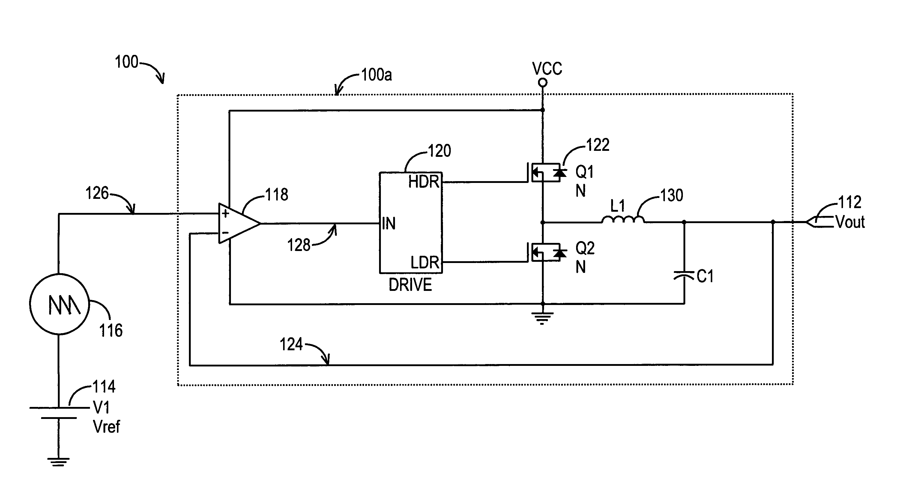
[0023]FIG. 1 is a circuit diagram that illustrates a fast transient response DC-DC converter 100 according to the invention. Generally, the DC-to-DC converter 100 stabilizes output voltage Vout 112 according to the reference signal at the input of the comparator. During a transient, the output load is in the process of switching from one DC state to another. The DC-to-DC converter 100 effectively reduces recovery time from a transient by modifying duty cycle in order to drive the Vout 112 to the desired steady state.

[0024]The DC-to-DC converter 100 uses a reference DC voltage source Vref 114, a reference signal generator 116, a comparator 118, a driver 120, and a pair of switches 122. The signal generator 116 generates a reference signal 126, which is preferably a 300 kHz saw-tooth signal, or alternatively, any shape of periodic signal such as a triangular signal or a sinus signal, with a DC offset determined by the DC voltage generated by Vref 114. The reference signal 126 is recei...


PUM


Abstract

A DC-to-DC converter includes a comparator, a driver, and a pair of switches. The comparator compares the output voltage with a reference voltage signal and generates a PWM signal. The driver drives the switches so as to force the output voltage to follow the reference signal. In a multiphase architecture, two or more such converter circuits are incorporated to minimize the output voltage ripple and further reduce the recovery time. In a two-phase architecture, two reference signals are phase-shifted by 180 degrees. In an N-phase architecture, the reference signals are phase-shifted by 360 / N degrees.

Description

CROSS-REFERENCE TO RELATED APPLICATIONS[0001]This application is a Continuation of application Ser. No. 10 / 262,537 filed Oct. 1, 2002 now U.S. Pat. No. 6,678,178, which itself is a Continuation of application Ser. No. 09 / 843,200 filed Apr. 25, 2001 now U.S. Pat. No. 6,459,602 which all claim the benefit of the filing date of U.S. Provisional Application Ser. No. 60 / 244,054 filed Oct. 26, 2000, all the teachings of which are incorporated herein by reference.TECHNICAL FIELD[0002]The invention generally relates to voltage converters, and more particularly to a direct-current (DC) to direct-current (DC) converter that exhibits improved transient response.BACKGROUND OF THE INVENTION[0003]Direct-current (DC) to direct-current (DC) converters are well-known in the field of electronics. Such circuitry or devices are typically employed to convert from one DC voltage level to another DC voltage level. They are used in a variety of environments. For instance, several kinds of such converters a...

Claims


Application Information

Patent Timeline
Patent Type & Authority Patents(United States)
IPC IPC(8): H02M7/44H02M3/158
CPCH02M1/15H02M3/1584H02M3/156H02M2003/1586H02M3/1586
Inventor LIPCSEI, LASZLO
Owner O2 MICRO INT LTD
Features
  • R&D
  • Intellectual Property
  • Life Sciences
  • Materials
  • Tech Scout
  • Unparalleled Data Quality
  • Higher Quality Content
  • 60% Fewer Hallucinations
Learn More