
Adaptive transmitter/receiver

Inactive Publication Date: 2006-04-18
NEC CORP
View PDF18 Cites 37 Cited by
  • Summary
  • Abstract
  • Description
  • Claims
  • Application Information

AI Technical Summary

Benefits of technology

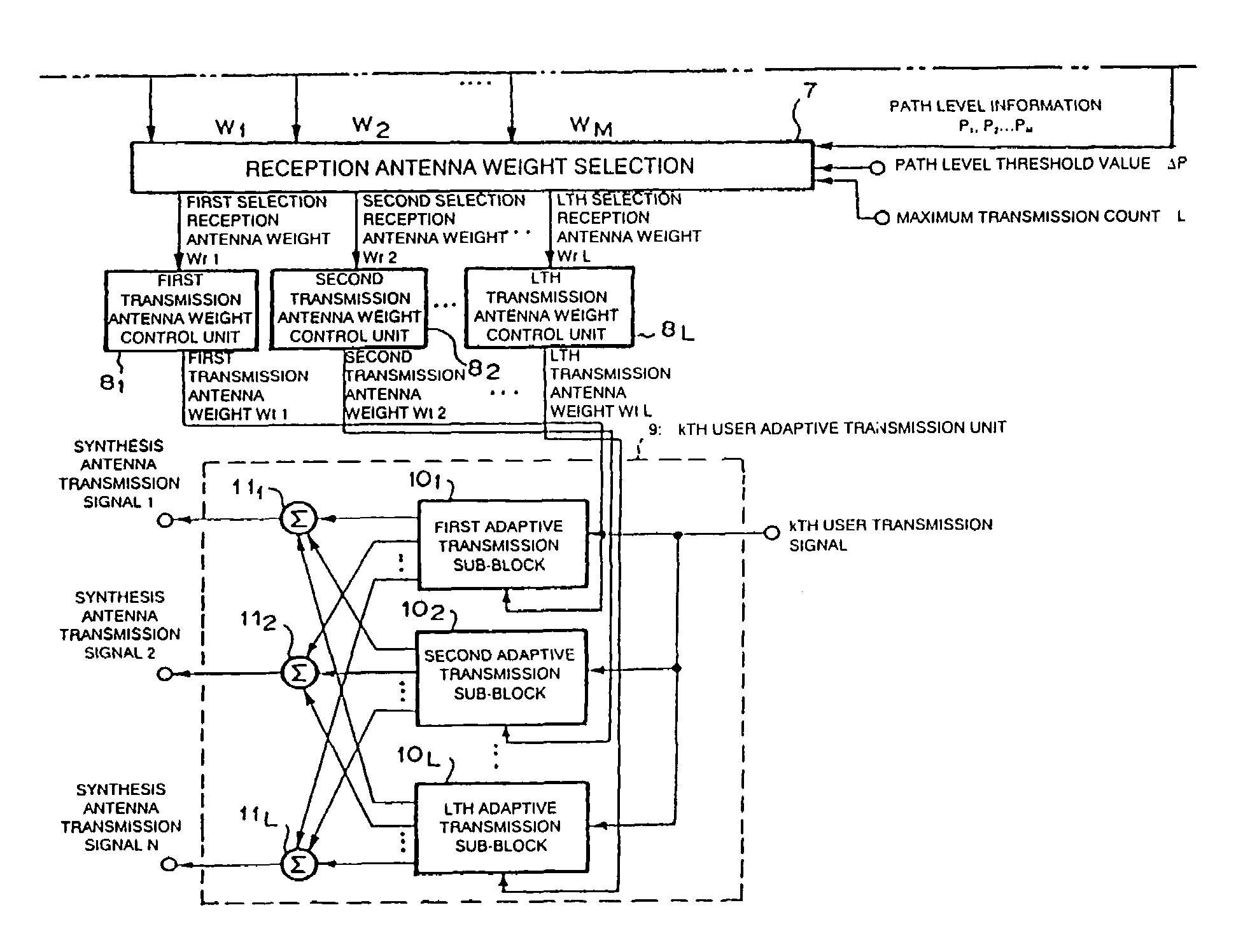
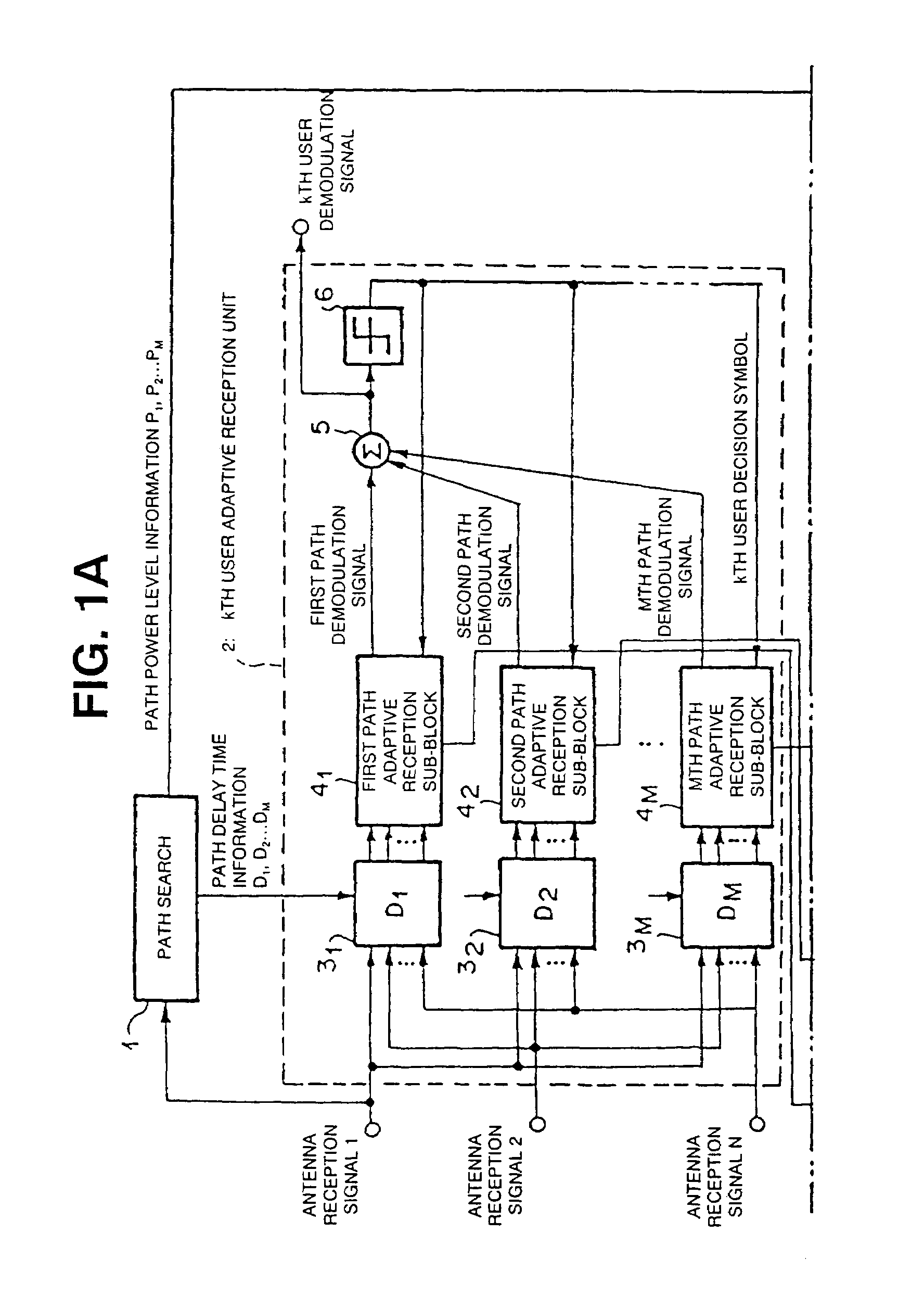
[0055]An adaptive transceiver device according to the present invention forms a directivity pattern for suppressing interference caused by another user or a multi-path in reception, estimates an arrival direction of a path from a reception antenna weight, predicts a transmission direction from the estimated arrival direction to generate a transmission antenna weight, and forms a directivity pattern for decreasing interference to another user in transmission.
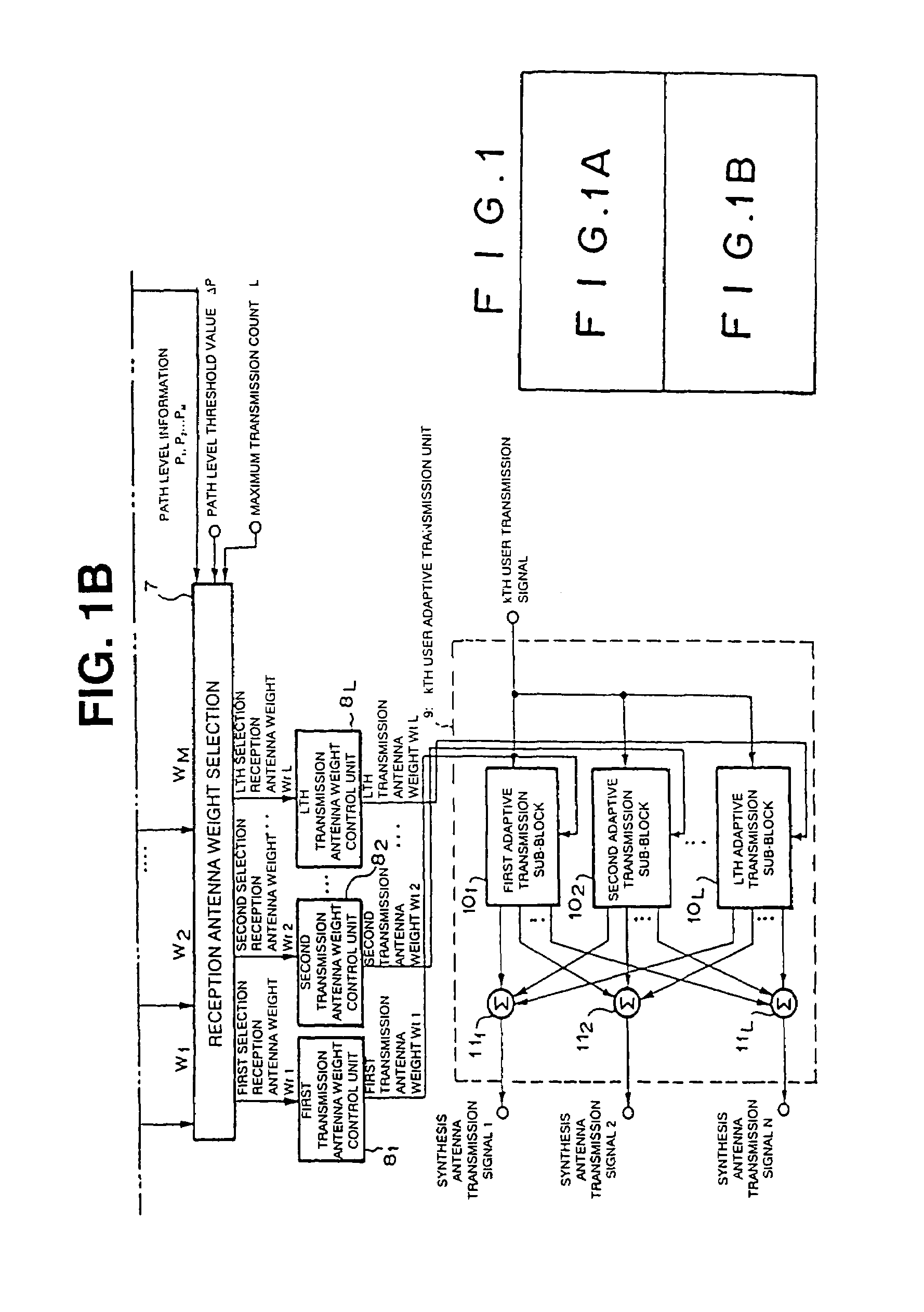
[0066]According to the present invention, Lmax is equal to or smaller than M, and L is equal to or smaller than Lmax. After some reception antenna weights having large path levels are selected, a transmission antenna weight is determined. Furthermore, when a plurality of paths are selected and transmitted, a transmission diversity effect can be obtained.
[0076]According to the present invention, a delay operation in transmission is not required to cause a mobile station to perform RAKE reception.
[0082]In the adaptive transceiver device according to the present invention, as is apparent from the disclosure, an arrival direction of a path is estimated from a reception antenna weight. Therefore, with respect to an adaptive reception unit for performing control based on the MMSE standards, a path arrival direction of a desired wave signal can be easily estimated. By predicting a transmission direction from the estimated arrival direction, a present arrival direction can be predicated by using a past arrival direction which is estimated late because of the control of the adaptive reception unit.

Problems solved by technology

However, the first disadvantage of the conventional technique is as follows.
In the reception unit of the conventional k-th user adaptive transceiver device shown in FIGS. 7 to 9, control for forming a directivity pattern which actively decreases a gain with respect to an interference wave cannot be performed, and performance is poorer than that in the control based on the MMSE standards.
In addition, when transmission and reception are controlled on the basis of an arrival direction estimation result, performance in the reception is not poor.
On the other hand, when control based on the MMSE standards is performed on the reception side, another arrival direction estimation means for transmission is required, and the structure disadvantageously increases in size.

Method used


Image

  • Adaptive transmitter/receiver
  • Adaptive transmitter/receiver
  • Adaptive transmitter/receiver

Examples


Embodiment Construction

[0094]Embodiments of the present invention will be described below with reference to the accompanying drawings. In this case, an adaptive transceiver device (CDMA adaptive transceiver device) in which a multiplexed signal is a code division multiple signal, the number of transmission / reception antenna is set to be N (N is an integer which is equal to or larger than 1), the number of users is set to be K (K is an integer which is equal to or larger than 1), the number of reception multi-paths per user is set to be M (M is an integer which is equal to or larger than 1), and the maximum transmission count is set to be L (L is equal to or larger than 1 and which is equal to or smaller than M) will be described below.

[0095]Referring to FIG. 1, a k-th user adaptive transceiver device according to the present invention is constituted by a first path search circuit 1, a first k-th user adaptive reception unit 2, a reception antenna weight selection circuit 7, first transmission antenna weig...


PUM


Abstract

There is provided an adaptive transceiver device which estimates a path arrival direction of a desired wave signal by using a reception antenna weight of a k-th user adaptive reception unit using a control method based on the minimum mean square error (MMSE) standards and which generates a transmission antenna weight on the basis of the path arrival direction. The adaptive transceiver device is characterized in that in reception, a directivity pattern for suppressing interference caused by another user or a multi-path is formed, an arrival direction of a path is estimated from the reception antenna weight, and a transmission direction is predicted from the estimated arrival direction to generate a transmission antenna weight, and in transmission, a directivity pattern for decreasing interference to another user is formed and transmitted.

Description

[0001]This application is a 371 of PCT / JP99 / 03478 filed on Jun. 29, 1999.TECHNICAL FIELD[0002]The present invention relates to an adaptive transceiver device for base station which removes interference caused by another user in reception and which decreases interference to another user in transmission by antenna directivity control and, more particularly, to an adaptive transceiver device using the CDMA (Code Division Multiple Access) system.BACKGROUND ART[0003]In recent years, in a cellular mobile communication system or the like, as a radio transmission method which can use a large number of channels in the same frequency band so that a large scriber's capacity can be expected, the CDMA (Code Division Multiple Access) system has been widely noticed. On the other hand, an adaptive transceiver device in which interference from another user or an interference caused by a delay wave is removed in transmission by using an adaptive antenna as an antenna for base station and in which no ...

Claims


Application Information

Patent Timeline
IPC IPC(8): H04B1/69H01Q3/26H04B1/10H04B7/06H04B7/08
CPCH04B7/0854H04B7/0615
Inventor MARUTA, YASUSHIYOSHIDA, SHOUSEI
Owner NEC CORP
Learn More