Systems and methods for setting up grid voltages in a tandem pin charging device

a technology of charging device and tandem pin, which is applied in the direction of electrographic process apparatus, instruments, corona discharge, etc., can solve the problems of high charge-up requirement, poor charging uniformity of photoreceptor, and high charge-up potential of the second device, so as to improve charging uniformity, improve charging uniformity, and improve the effect of charging uniformity

Inactive Publication Date: 2006-04-18
XEROX CORP
View PDF9 Cites 6 Cited by
  • Summary
  • Abstract
  • Description
  • Claims
  • Application Information

AI Technical Summary

Benefits of technology

[0012]Static set points generally cannot be used to set the grid voltage of the first and second charging devices because such static set points cannot meet the performance requirements for charging photoreceptors. Variations in charging performance may occur, for example, because of deviations in mechanical tolerances, variations in environmental conditions, such as, for example, temperature, pressure, and / or humidity, and the like. In addition, mechanical tolerance deviations, as well as environmental variations, vary over time. Thus, ultimate copy quality is affected over time, as a result of mechanical and environmental variations. This results in increased service calls related to copy quality problems. As such, there is a need for a low cost solution for controlling the offset voltage.
[0016]This invention separately provides systems and methods for enabling the use of low cost devices such as pin scorotrons to replace higher cost devices to enhance copy quality and reduce service calls related to copy quality problems.
[0018]In various exemplary embodiments, systems and methods according to this invention may be used to compensate for variations in charging conditions due to mechanical tolerances and / or environmental conditions. For example, during machine warm-up, the first charging unit of the dual pin scorotron system is enabled, while the second charging unit is disabled. Then, the grid voltage of the first charging unit is started at a low setting and is increased in desired increments. An electrostatic voltage meter (ESV) may be used to measure the interim photoreceptor potential after the photoreceptor is charged by the first charging device. The measured interim photoreceptor potential from the ESV is used in a closed-loop feed-back system to adjust the first voltage of the first charging unit. In various exemplary embodiments, these closed loop feed-back adjustment systems and methods enable the interim photoreceptor potential, after passing the first charging device, to be about 40 volts less than the second grid voltage and final photoreceptor potential. Thus, the interim photoreceptor potential, after passing the first charging device, is at a desirable point for the second charging device to add additional charge to the photoreceptor and to reduce voltage nonuniformity.

Problems solved by technology

If the offset voltage is too small, the overshoot voltage of the first device results in the photoreceptor charging potential being higher than the grid voltage of the second device.
Consequently, the charging uniformity on the photoreceptor will be poor, because the system fails to benefit from the charge uniformity the second charging device is able to create.
If the offset voltage is too large, a high charge-up requirement is imposed on the second device.
Because the second charging device is a lower slope device, it may be not be capable of achieving the ultimate desired charge potential on the photoreceptor from all of the pin emitters, thus reducing the charging uniformity of the charge on the photoreceptor.
Static set points generally cannot be used to set the grid voltage of the first and second charging devices because such static set points cannot meet the performance requirements for charging photoreceptors.
Thus, ultimate copy quality is affected over time, as a result of mechanical and environmental variations.
This results in increased service calls related to copy quality problems.

Method used


Image

  • Systems and methods for setting up grid voltages in a tandem pin charging device
  • Systems and methods for setting up grid voltages in a tandem pin charging device
  • Systems and methods for setting up grid voltages in a tandem pin charging device

Examples


Embodiment Construction

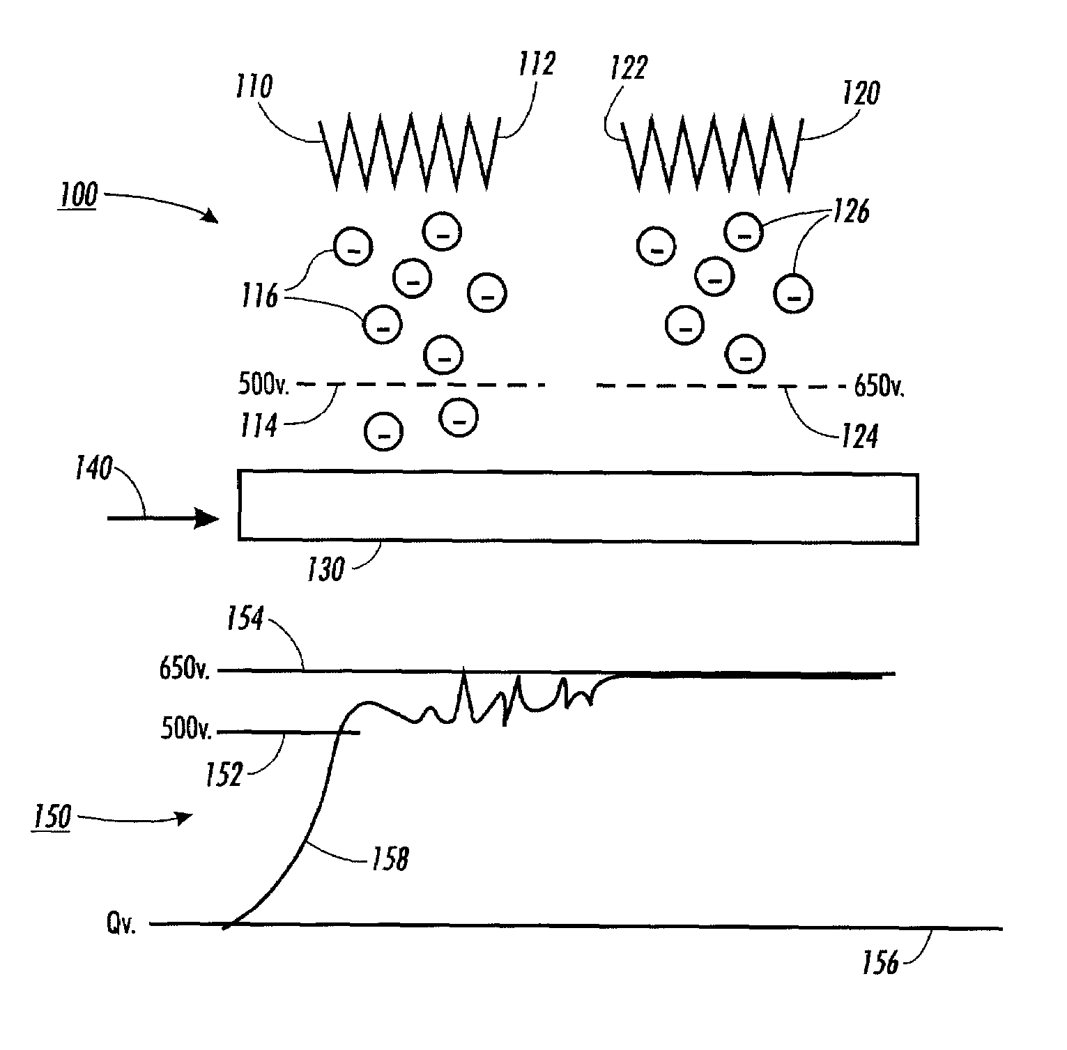
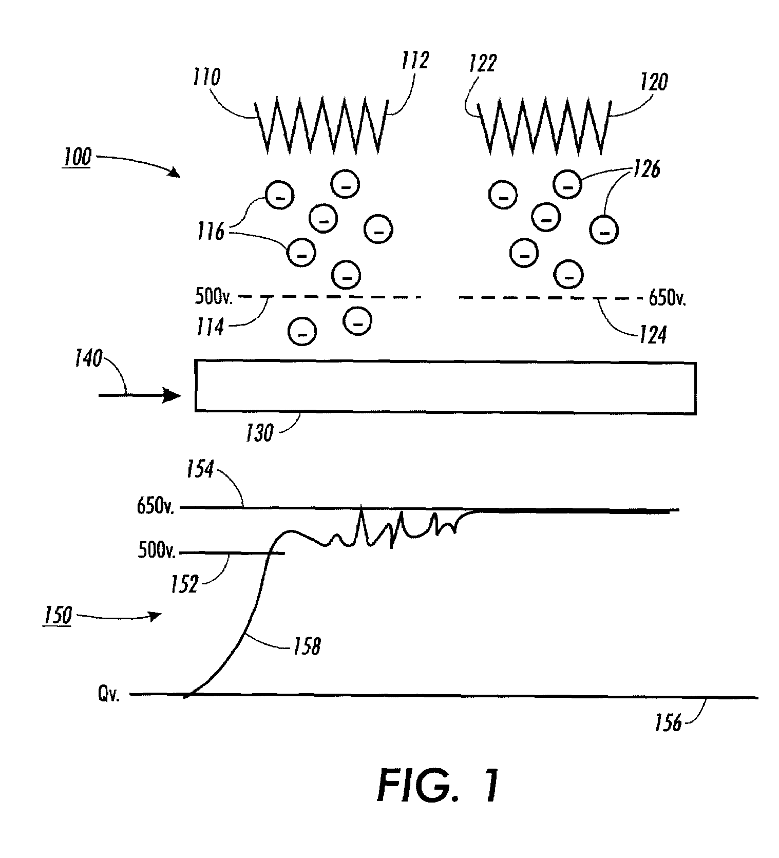
[0027]FIG. 1 illustrates one exemplary embodiment of a dual pin scorotron system 100 and a graph 150 that illustrates the measured voltage on a photoreceptor 130 as the photoreceptor 130 passes a first charging unit 110 and a second charging unit 120 of the dual pin scorotron system 100. In a typical dual pin scorotron system 100, ions 116 generated from a pin scorotron 112 of the first charging unit 110 are accelerated by a field force past a first grid 114 to reach the photoreceptor 130, thus increasing the surface potential of the photoreceptor 130. When the surface potential V1C of the photoreceptor 130 reaches the same voltage Vgrid1 as the voltage on the first grid 114, there is no electrostatic field between the first grid 114 and the photoreceptor 130. However, since the ions 116 have high residual momentum as they approach the first grid 114 from the first charging unit 110, the ions 116 will continue to penetrate the first grid 114 and build up a space charge. This extra s...


PUM


Abstract

Systems and methods for setting up grid voltage for a tandem pin charging device for charging a photoreceptor in a xerographic printing machine. A charge-generating emitter ratio of a first charging unit is determined and a first grid voltage is set based on the charge-generating emitter ratio of the first charging unit. A charge-generating emitter ratio of a offset voltage is then determined and a second grid voltage is set, based on the determined charge-generating emitter ratio of the offset voltage. A final voltage of a photoreceptor is then compared with a final target voltage.

Description

BACKGROUND OF THE INVENTION[0001]1. Field of the Invention[0002]This invention relates to systems and methods for controlling process parameters for a xerographic printing machine.[0003]2. Description of Related Art[0004]The use of charging devices for photoreceptors in xerographic printing is well known in the art. Typically, such charging devices may be one or more of a corotron, a dicorotron, a pin corotron, a scorotron, a discorotron, and / or a pin scorotron. Such charging devices may include a chamber arranged with one or more charge-generating emitters such as, for example, a wire, a dielectric wire, or a pin array. Some charging devices may also include a control grid to regulate and control the charge provided to the photosensitive member. In this way, the photosensitive member may receive a uniform charge at a desired potential.[0005]As known in the art, a key characteristic of a charging device is the di / dV ratio or charge generating emitter ratio of the charge-generating e...

Claims


Application Information

Patent Timeline
Patent Type & Authority Patents(United States)
IPC IPC(8): G03G15/02G03G15/16
CPCG03G15/0266G03G2215/028
Inventor SEKOVSKI, DAVIDSONG, JING QINGO'BRIEN, JOHN FRANCISRANDALL, STEPHEN FERRISMO, SONG-FENG
Owner XEROX CORP
Why Eureka
Try Eureka