
MRI shoulder coil

a shoulder coil and magnetic resonance imaging technology, applied in the field of magnetic resonance imaging (mri) radio frequency (rf) coils, can solve the problems of large coils, reducing the signal-to-noise ratio (snr), and not providing optimized snr

Active Publication Date: 2006-04-18
GENERAL ELECTRIC CO
View PDF6 Cites 32 Cited by
  • Summary
  • Abstract
  • Description
  • Claims
  • Application Information

AI Technical Summary

Problems solved by technology

A large coil, however, produces a lower signal-to-noise ratio (SNR) if it is also used for reception, mainly because of its greater distance from the signal-generating tissues being imaged.
Several problems exist in existing MRI shoulder coils.
In a horizontal bore MRI scanners, the quadrature coils of U.S. Pat. Nos. 5,343,862 and 5,351,688) do not provide optimized SNR due to the required separation of the anterior and posterior elements.
Strong coupling to each other will result in poor isolation and therefore poor combined image quality.
Keeping the two elements far enough apart so that the sensitivity at the middle region becomes weak enough to maintain acceptable isolation will lead to poor penetration in combined image.
Unfortunately, the shoulder coils described in U.S. Pat. Nos. 5,343,862 and 5,351,688 will not function in open MRI scanners because of the direction of the magnetic axes of the disclosed coils.
The linear coil can have good signal at center of the loop, but the coverage, uniformity and penetration are too poor for adequate clinical application, even at the humeral head, the center of region of interest for shoulder imaging.

Method used


Image

  • MRI shoulder coil
  • MRI shoulder coil
  • MRI shoulder coil

Examples


Embodiment Construction

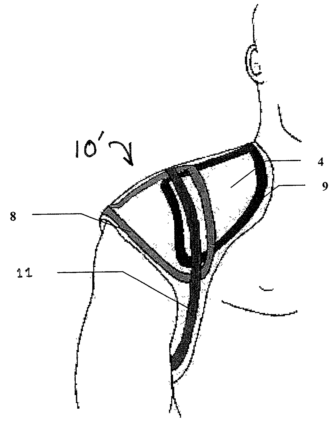
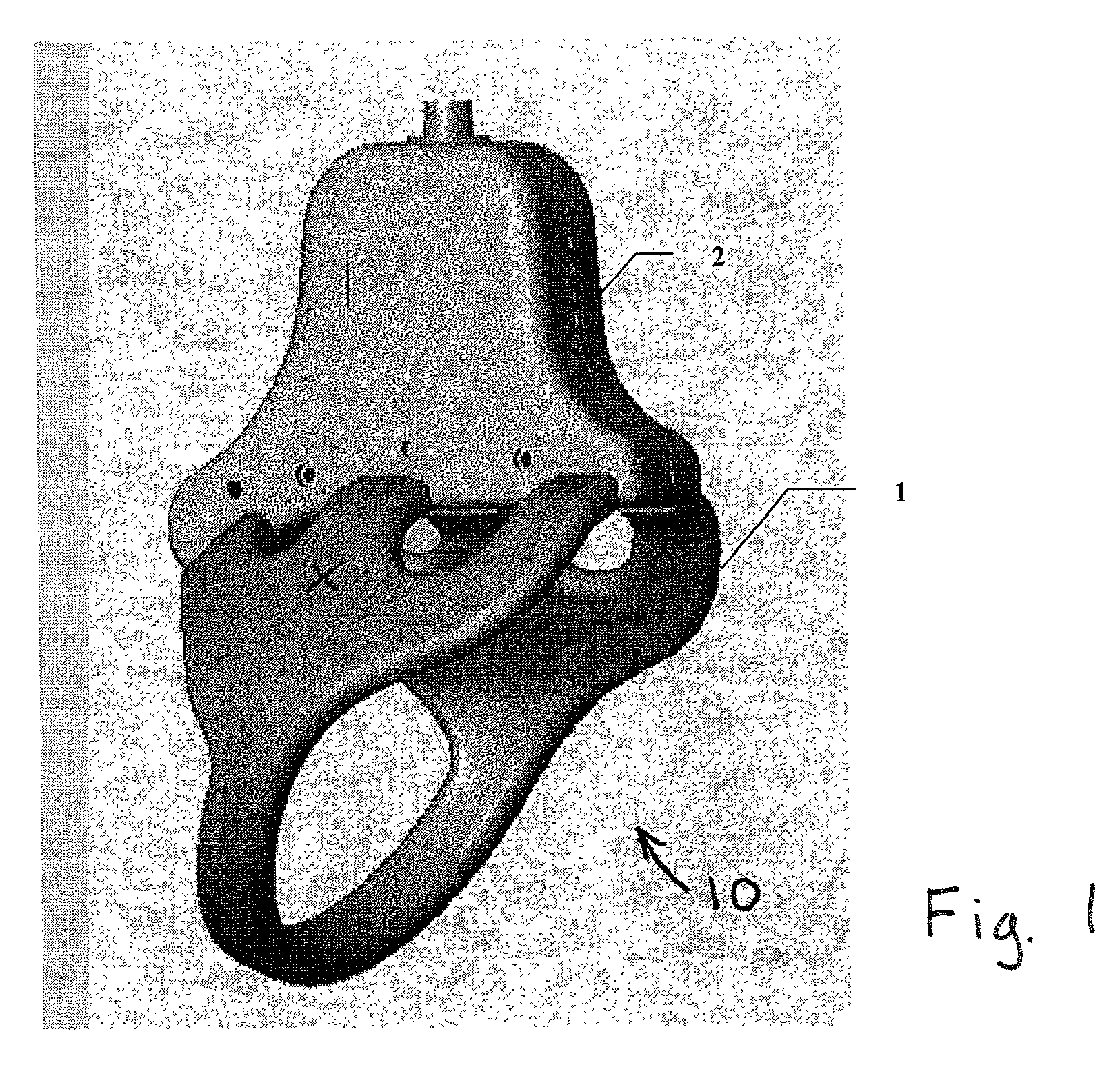
[0024]Referring to FIG. 1, a quadrature coil 10 for a human shoulder includes a frame 1 and a housing 2. The frame 1 may be, for example, formed of flexible plastic, covered with soft foam and coated with a smooth vinyl. The frame 1 is optimized for conforming to the top of a human shoulder. It may be produced, for example, in three sizes (e.g., small, medium, large) to a enable imaging of 100 percent of the patient population. The housing 2 may be, for example, formed of a rigid plastic. As more fully described below, the electrical components of the coil may be located within the frame 1 and housing 2.

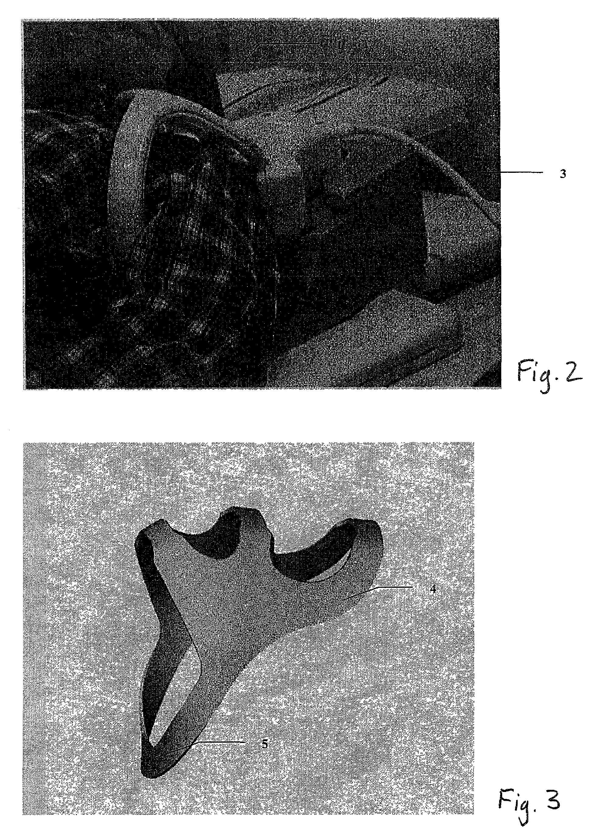
[0025]Referring to FIG. 2, the coil 10 is shown positioned on a human shoulder for imaging. A foam pad 3, for example, may be used on the left side of the patient to help position the coil 10 on the patient. To image the other shoulder of the patient, the coil 10 may be inverted and a similar foam pad but with a reversed left-right symmetry used.

[0026]Referring to FIG. 3, a possible ...


PUM


Abstract

A MRI quadrature coil for imaging a human shoulder has a first coil shaped to conform to the top of the shoulder and a second coil adapted to encircle the shoulder. The second coil has a magnetic axis generally orthogonal to that of the first coil.

Description

CROSS-REFERENCE TO RELATED APPLICATION[0001]This application claims the benefit of U.S. provisional patent application Ser. No. 60 / 284,477 filed Apr. 18, 2001.BACKGROUND OF THE INVENTION[0002]The present invention relates to magnetic resonance imaging (MRI) radio frequency (RF) coils and, in particular, to a coil for imaging a human shoulder.[0003]MRI utilizes hydrogen nuclear spins of the water molecules in the human body, which are polarized by a strong, uniform, static magnetic field of the main magnet (named B0—the main magnetic field in MRI physics). The magnetically polarized nuclear spins generate magnetic moments in the human body. The magnetic moments point in the direction of the main magnetic field in a steady state, and produce no useful information if they are not disturbed by any excitation.[0004]The generation of a nuclear magnetic resonance (NMR) signal for MRI data acquisition is accomplished by exciting the magnetic moments with a uniform RF magnetic field (called ...

Claims


Application Information

Patent Timeline
IPC IPC(8): A61B5/055
CPCA61B5/055G01R33/3678A61B5/4528A61B2562/164
Inventor ZHANG, VERA FENGLING
Owner GENERAL ELECTRIC CO
Learn More