Signal transfer method and apparatus

a technology of signal transfer and a switch, applied in the direction of transmission systems, instruments, analogue-digital converters, etc., can solve the problems of high inefficiency of arrangement, small copper width of each loop coil, and system being relatively inefficient at powering the stylus

Inactive Publication Date: 2011-03-15
SINNAPTIX
View PDF214 Cites 31 Cited by
  • Summary
  • Abstract
  • Description
  • Claims
  • Application Information

AI Technical Summary

Benefits of technology

[0009]One aspect of the present invention provides an apparatus for transferring signa

Problems solved by technology

However, this arrangement is highly inefficient because there are a large number of loop coils, each of which is formed from a small number of conductor loops printed on a printed circuit board (PCB) and therefore the width of copper available for each loop coil can only be small.
As is well-known to those skilled in the art, such a small volume of copper results in the system being relatively inefficient at powering the stylus when it is above the coil.
With this arrangement, eddy current losses in both the screening material and the bezel represent significant sources of power loss.
Although the bezel may be slit to prevent such eddy

Method used


Image

  • Signal transfer method and apparatus
  • Signal transfer method and apparatus
  • Signal transfer method and apparatus

Examples


Embodiment Construction

Overview of Digitising System

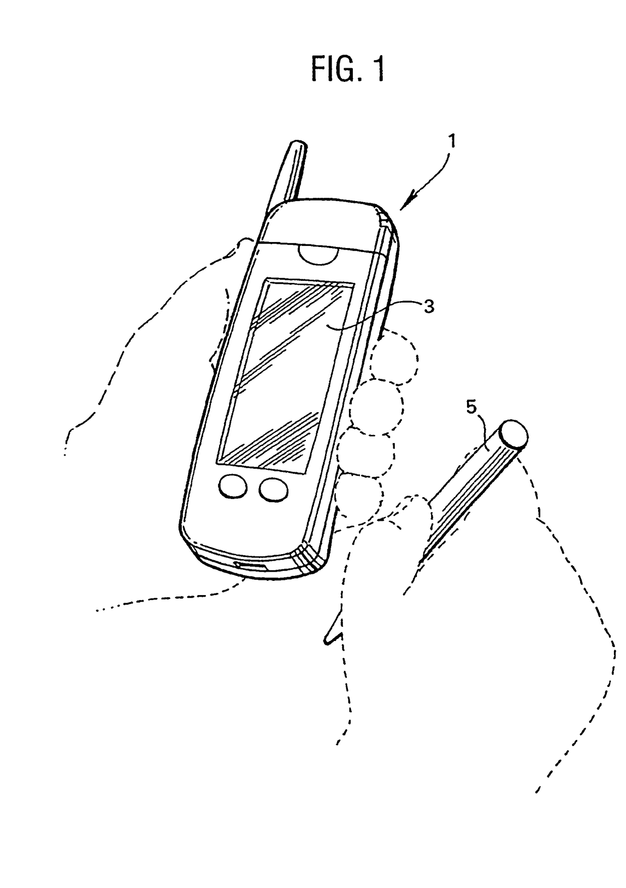
[0047]FIG. 1 shows a handheld battery-powered mobile cellular telephone 1 which employs an x-y digitising system (not shown) that is associated with a liquid crystal display (LCD) 3 of the telephone 1. The x-y digitising system is operable to detect the presence and x-y position of a resonant stylus 5 relative to the LCD 3. The position of the signals output from the digitising system are used by the mobile telephone to control information that is displayed on the LCD 3 and to control the operating function of the telephone 1.

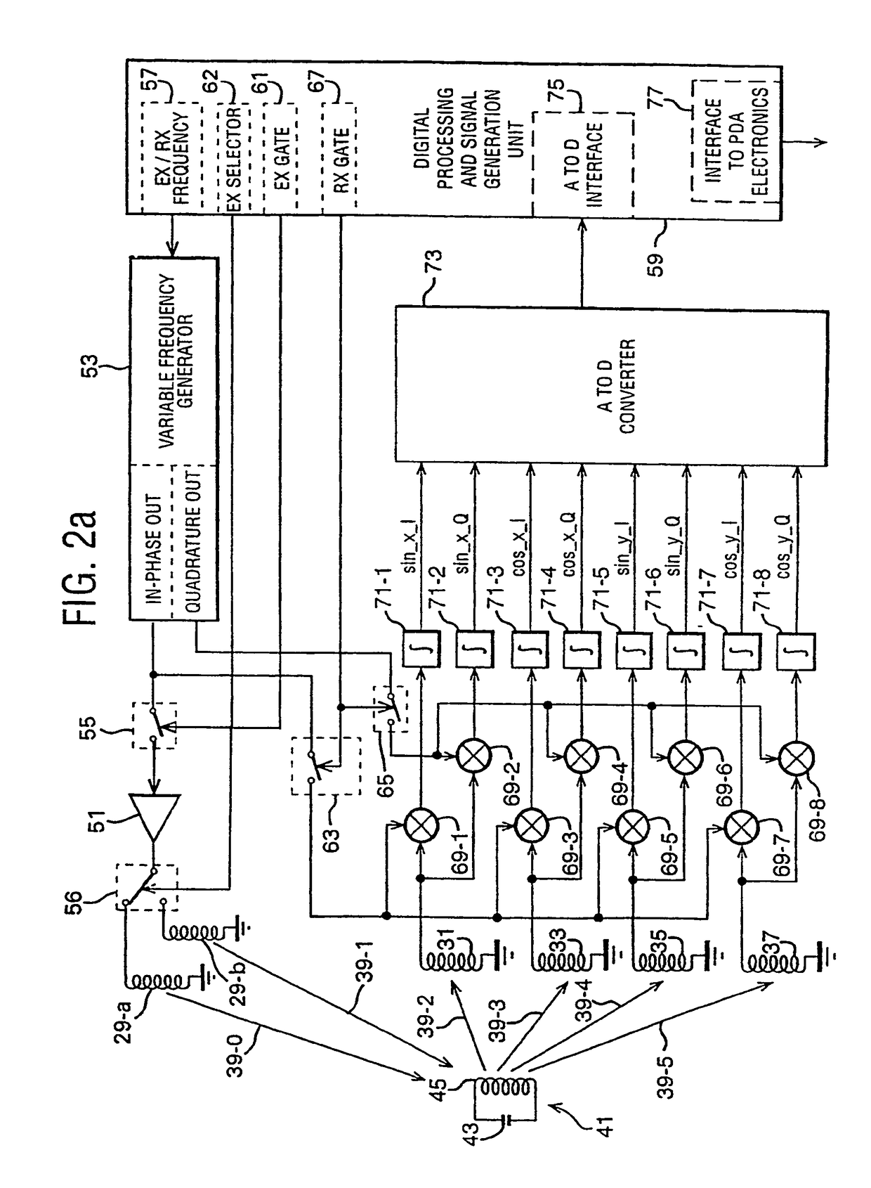
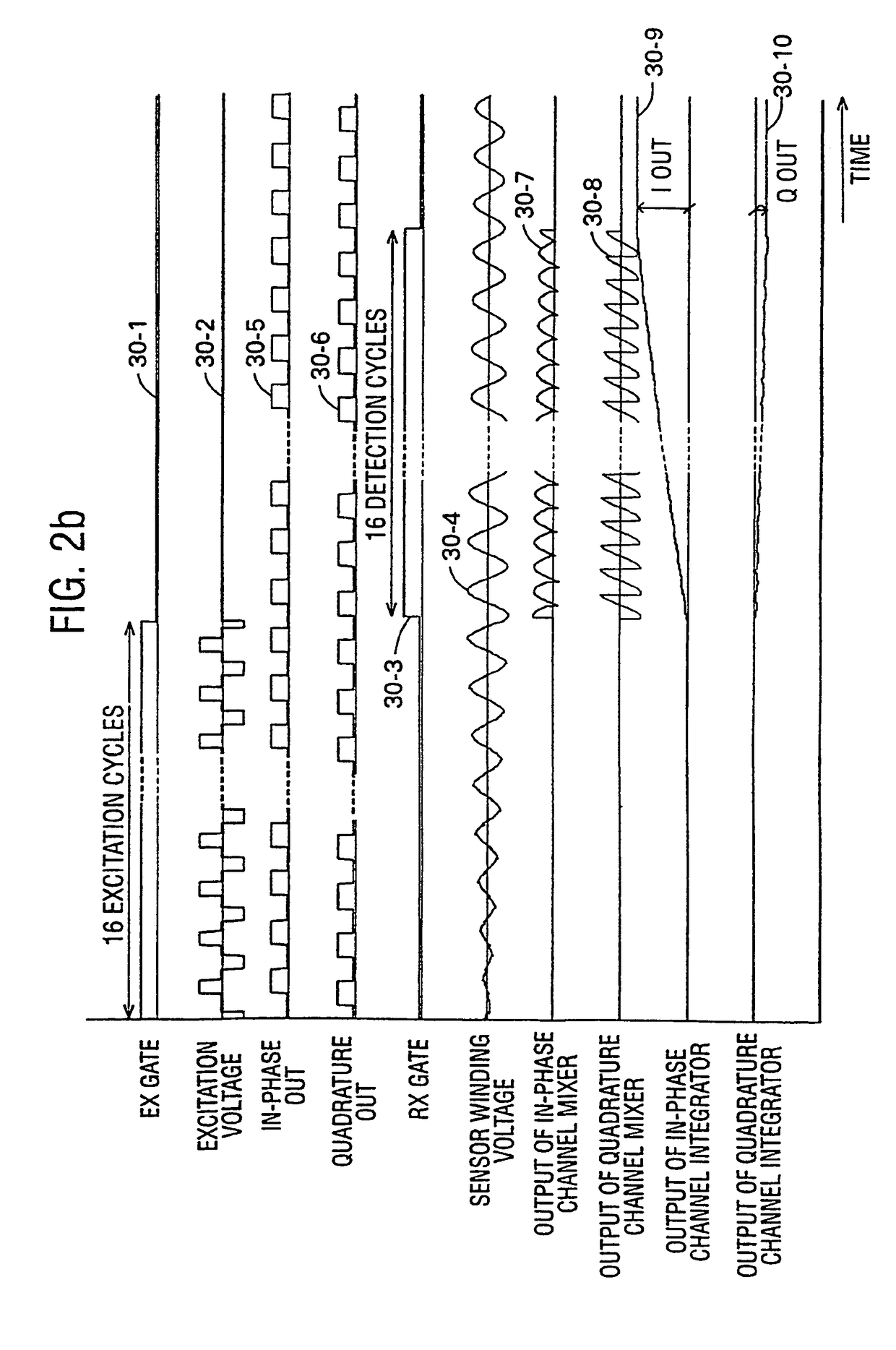
[0048]FIG. 2a schematically illustrates a functional block diagram of the digitising system's processing electronics and FIG. 2b illustrates some of the signals in the digitising system during an excitation and receive cycle. FIG. 2a also illustrates the way in which excitation windings and the sensor windings interact with the resonant stylus 5. In particular, FIG. 2a schematically shows two excitation windings 29-a and 29-b, two x...


PUM


Abstract

An x-y digitising system is described which operates with a resonant stylus. The x-y digitising system includes an excitation winding for energising the resonant stylus and a number of sensor windings for receiving a signal re-radiated by the resonant stylus when energised. At least one of the excitation winding and the sensor winding is arranged to have its effective magnetic axis non-othogonal to the working area of the x-y digitising system. With this arrangement, improved energy transfer between the x-y digitising system and the resonant stylus can be achieved and/or improved position measurement accuracy can be obtained.

Description

CROSS-REFERENCE TO RELATED APPLICATIONS[0001]This application is the U.S. national phase of international application PCT / GB03 / 02432 filed Jun. 5, 2003 which designated the U.S. and claims benefit of GB 0212889.0, dated Jun. 5, 2002 and GB 0302298.5, dated Jan. 31, 2003, the entire content of which is hereby incorporated by reference.BACKGROUND[0002]1. Technical Field[0003]The present invention relates to an apparatus for and a method of transferring signals between two devices. The invention has particular application in portable, battery-powered devices such as personal digital assistants, mobile telephones, tablet PCs, web browsers, etc.[0004]2. Related Art[0005]Inductive digitiser systems used in portable computer devices work by transferring power to a moveable stylus inductively. When powered, the stylus in turn transmits a signal back to the digitiser tablet and this is detected by a number of detecting elements to determine the position and status of the stylus. The return s...

Claims


Application Information

Patent Timeline
IPC IPC(8): G06F3/033G06F3/046G06F3/0354
CPCG06F3/03545G06F3/046
Inventor ELY, DAVID THOMAS ELIOT
Owner SINNAPTIX
Why Eureka
Try Eureka