Instantaneous power floating frame controller

a floating frame controller and controller technology, applied in the direction of dynamo-electric converter control, motor/generator/converter stopper, dynamo-electric gear control, etc., can solve the problems of unreliable rotor position sensors and difficult mounting of rotor position sensors to the motors

Active Publication Date: 2006-07-11
HONEYWELL INT INC
View PDF14 Cites 30 Cited by
  • Summary
  • Abstract
  • Description
  • Claims
  • Application Information

AI Technical Summary

Problems solved by technology

Such rotor position sensors, however, can be unreliable due to mechanism alignment problems and temperature incompatibility problems between the stator windings and electronic components such as the Hall effect devices.
Moreover, the rotor position sensors can be difficult to mount to the motor during motor assembly, especially for multi-pole motors.

Method used


Image

  • Instantaneous power floating frame controller
  • Instantaneous power floating frame controller
  • Instantaneous power floating frame controller

Examples


Embodiment Construction

[0013]Embodiments of the present invention are more specifically set forth in the following description, with reference to the appended drawings. In the following description and accompanying drawings like elements are denoted with similar reference numbers. Further, well-known elements and related explanations are omitted so as not to obscure the inventive concepts presented herein.

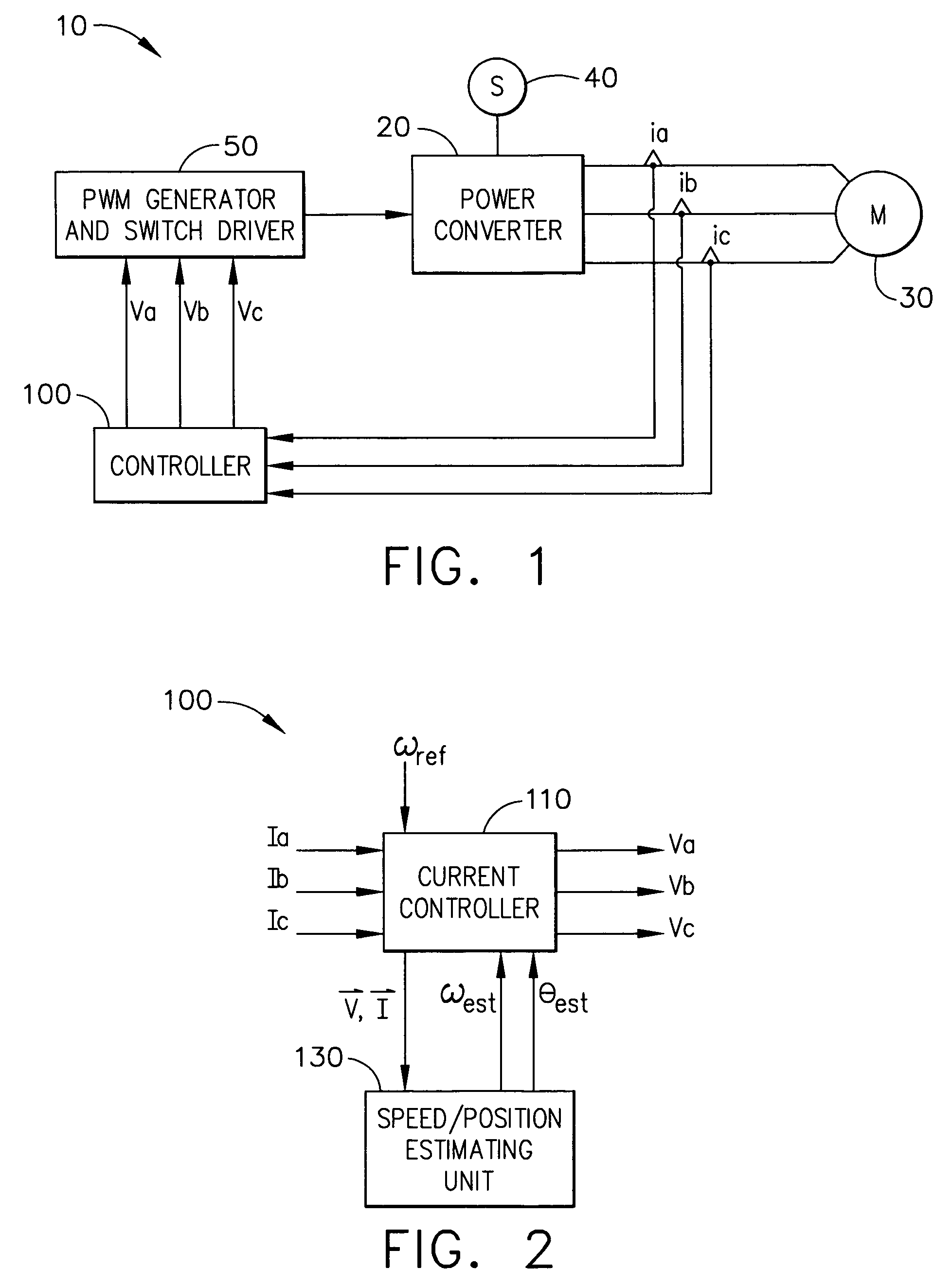
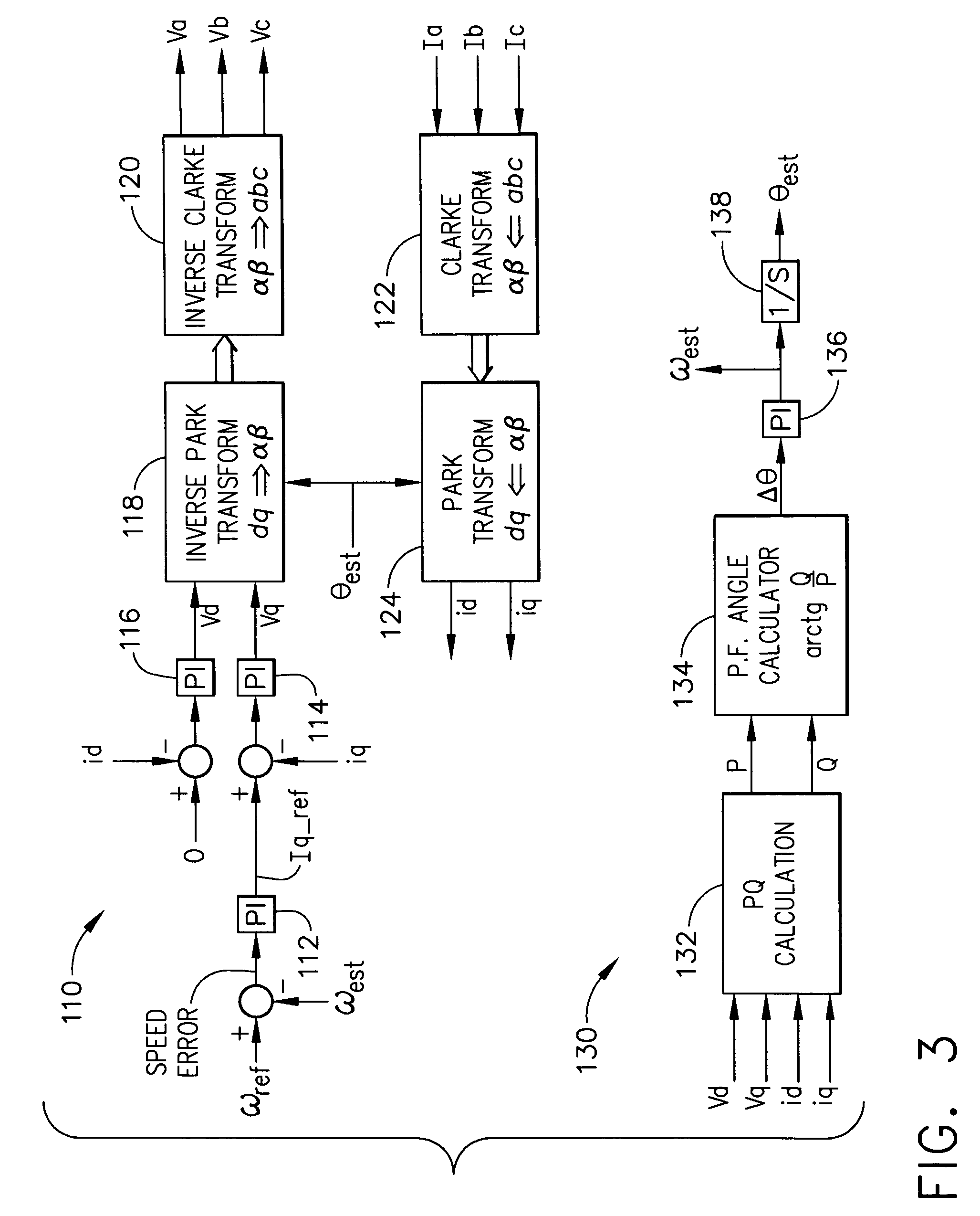
[0014]In accordance with aspects of the present invention, a FFC-based control apparatus measures multi-phase line current, calculates a reference frame that synchronizes with rotor position / speed based on vector control and sensorless rotor position / speed estimation. In accordance with an implementation of the present invention, instantaneous power, including imaginary power (O) and real power (P), is calculated to determine rotor position / speed. The synchronized reference frame is used to control a power converter. The instantaneous power floating frame controller can drive a synchronous machine withou...


PUM


Abstract

The present invention relates to a method of controlling a power converter (20) of a synchronous machine system (10), the method comprising sampling phase-current values between the power converter (20) and the synchronous machine (30); selecting a reference frame; regulating a current vector to align with the selected reference frame, the selected reference frame having a direct-axis component and a quadrature-axis component; estimating rotor speed and position as a function of instantaneous power; adjusting the selected reference frame, based on estimated rotor position, to synchronize the selected reference frame with a magnetic axis of the rotor, thereby generating a synchronized floating frame; and applying the synchronized floating frame to control the power converter (20). The present invention also related to a power converter controlling apparatus (100) for controlling a power converter (20) of a synchronous machine system (10) without use of a machine position sensor.

Description

RELATED APPLICATION[0001]This application claims priority under 35 USC §119(e) of Provisional Application No. 60 / 557,710 filed Mar. 31, 2004, the entire contents of which are herein incorporated by reference.FIELD OF THE INVENTION[0002]The present invention relates to electrical power conversion, and more particularly to a controller for a power converter, such as an inverter of a synchronous AC motor drive system.BACKGROUND OF THE INVENTION[0003]A synchronous AC motor typically utilizes rotor position sensors to provide information regarding the position of the motor's rotor with respect to the motor's stator windings. Such positional information allows for proper conversion of power that is supplied to the stator windings. Rotor position sensors such as Hall effected devices are typically mounted in the stator, proximate the stator winding, to provide intelligence regarding rotor position. Such rotor position sensors, however, can be unreliable due to mechanism alignment problems ...

Claims


Application Information

Patent Timeline
Patent Type & Authority Patents(United States)
IPC IPC(8): H02P1/46H02P1/50H02P23/00H02P3/18H02P6/00H02M7/00H02P21/14
CPCH02P21/0042H02P21/146H02P2207/05H02P21/18H02P21/26
Inventor HUGGETT, COLINWANG, ZHENGZHOU, GEORGE YOU
Owner HONEYWELL INT INC
Why Eureka
Try Eureka