

Method and device for controlling an internal combustion engine
- Summary
- Abstract
- Description
- Claims
- Application Information
AI Technical Summary
Benefits of technology
Problems solved by technology
Method used
Image

Examples
Embodiment Construction
[0026]Elements of the same design and function are identified in all the figures with the same reference symbol.
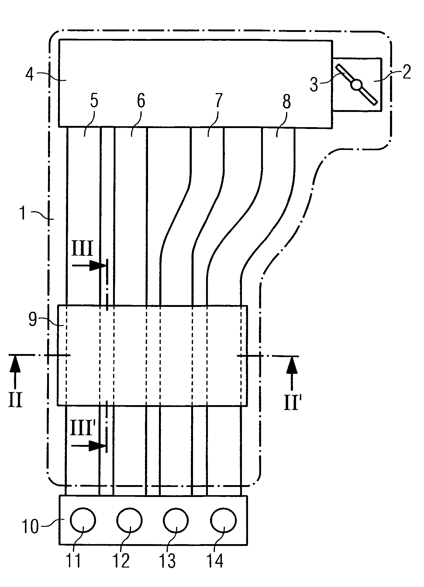
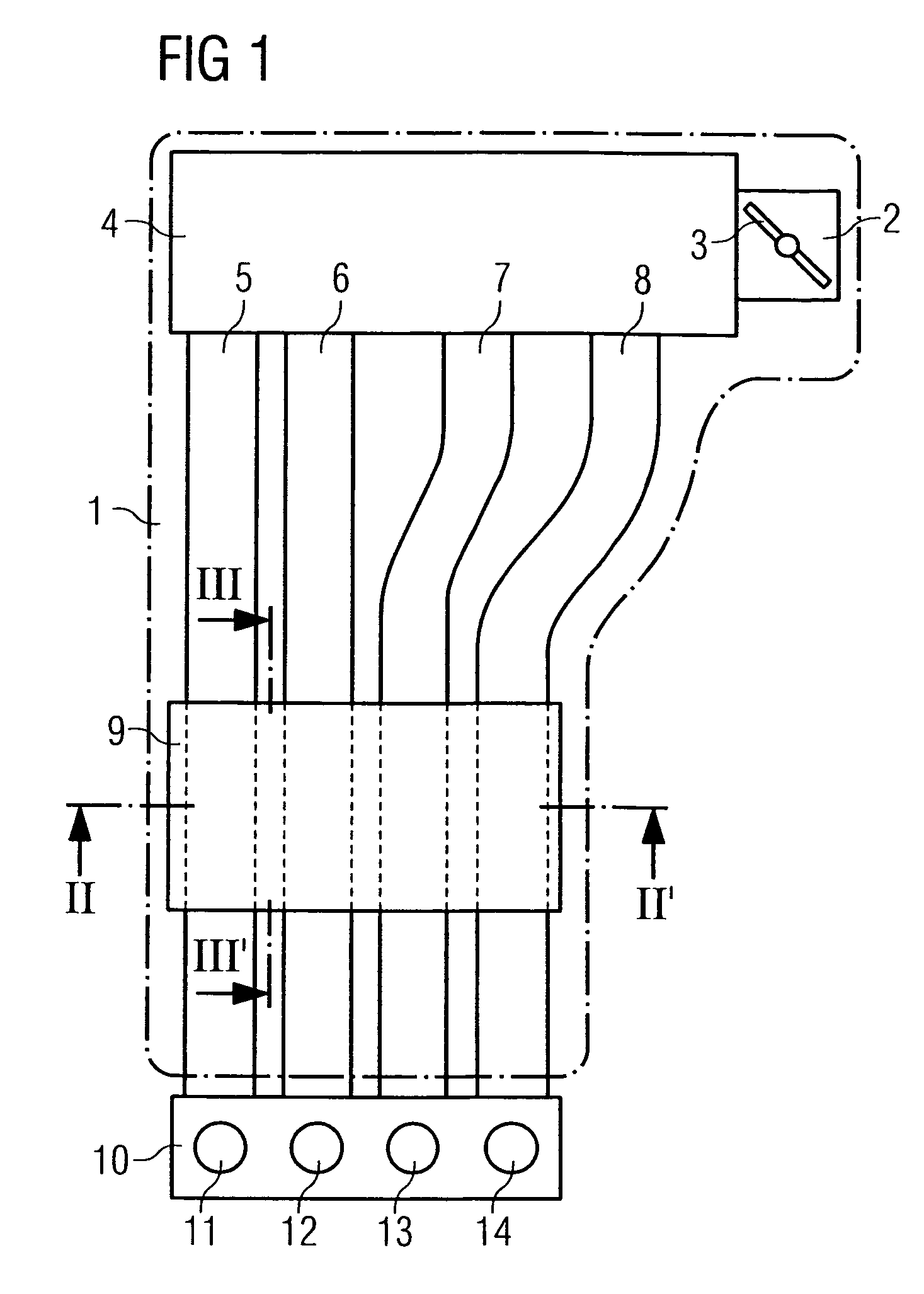
[0027]An intake device 1 (FIG. 1) of an internal combustion engine has an intake air duct 2, in which a throttle valve 3 is preferably arranged. The intake air duct 2 communicates with a first manifold 4, from which intake pipes 5, 6, 7, 8 are again routed to intakes 11, 12, 13, 14 of an engine block. A second manifold 9 is embodied downstream of the first manifold 4 and upstream of the intakes 11 to 14. In the range of the second manifold 9, actuators embodied for closing or opening at least one opening of the intake pipes up to a hollow body are embodied as switching flaps 20, 21, 22. Thus, in this embodiment the hollow body is the volume up to the neighboring intake pipe 5 to 8 in each case. However, in an alternative embodiment, it can also be an additional volume. However, the hollow body can also directly be the first manifold 4 or communicate directly with the first...
PUM
 Abstract
Description
Claims
Application Information