Eureka AIR delivers breakthrough ideas for toughest innovation challenges, trusted by R&D personnel around the world.

Charging station for charging electric vehicles with distributed energy measurement and method

Active Publication Date: 2022-03-08
SIEMENS AG
View PDF15 Cites 1 Cited by
  • Summary
  • Abstract
  • Description
  • Claims
  • Application Information

AI Technical Summary

Benefits of technology

The present patent provides a charging station with a measured value capture computer that can capture the amount of energy delivered to electric vehicles through the use of rectifier branches. This computer can uniquely assign the energy to a specific vehicle, even if the rectifier branches are dynamically assigned. The computer can also detect the connection between the rectifier branches and the charging points, as well as the vehicle identification during charging. The charging procedure control unit can determine the amount of power needed and control the connection between the rectifier branches and the charging points accordingly. These features improve the utilization of the charging station, reduce investment costs, and space requirement.

Problems solved by technology

An output-side DC measurement of the output electrical energy inevitably results in the measuring devices also having to be designed for the entire dynamic range.
This is due to power losses and different battery voltages.
In this case, the consideration of the error propagation of two variables multiplied by one another has a particularly unfortunate effect.
There are also further complications in the measurement, for example, caused by ripple currents.
However, this requirement proves to be technically difficult for several reasons.
Furthermore, the dynamic connection of further branches increases the system losses, whereas disconnection reduces the system losses.
In contrast, in the case of the relatively short durations of a charging operation in electromobility, only small amounts of output energy therefore result even in the case of rather large powers.
If a rectifier branch were used only for a very short peak load of sometimes less than a minute, in particular, this would result in corresponding distortion of the measurement result on account of the resolution of the energy meter.
However, it may be expected that higher requirements will be required within the scope of the conformity assessments of the quick charging infrastructure and legal transitional periods will not be extended.

Method used


Image

  • Charging station for charging electric vehicles with distributed energy measurement and method
  • Charging station for charging electric vehicles with distributed energy measurement and method
  • Charging station for charging electric vehicles with distributed energy measurement and method

Examples


Embodiment Construction

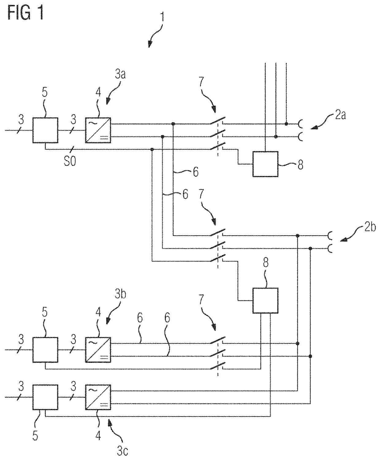
[0036]FIG. 1 shows a schematic illustration of a charging apparatus 1. The charging apparatus 1 is used to charge electrical energy stores of electric vehicles or electrically driven vehicles. For this purpose, the charging apparatus 1 includes charging points 2a, 2b to which the electric vehicles may be connected. In the present example, the charging station 1 includes a first charging point 2a and a second charging point 2b. Provision may also be made for the charging station 1 to have at least three charging points 2a, 2b. In addition, the charging station 1 includes at least two rectifier branches 3a, 3b, 3c. In the present example, the charging station 1 includes a first rectifier branch 3a, a second rectifier branch 3b, and a third rectifier branch 3c. The respective rectifier branches 3a, 3b, 3c may be used to convert a three-phase AC voltage or an alternating current into a DC voltage or a direct current. The electrical energy stores of the electric vehicles at the respectiv...


PUM


Abstract

The present disclosure relates to a charging station for charging electric vehicles. The charging station includes: at least two charging points, which are each connectable to an electric vehicle for charging an electric energy store of the electric vehicle; at least two rectifier branches for providing electrical energy, the rectifier branches being electrically connectable to the charging points and the electrical connection being switchable between at least one of the rectifier branches and the charging points; at least one energy meter for providing meter values which describe the electrical energy provided by the rectifier branches; and at least one meter value acquisition computer configured to determine, for each of the charging points, the amount of the electrical energy provided by the rectifier branches electrically connected to the charging point based on the meter values of the at least one energy meter.

Description

[0001]The present patent document is a § 371 nationalization of PCT Application Serial No. PCT / EP2019 / 052481, filed Feb. 1, 2019, designating the United States, which is hereby incorporated by reference, and this patent document also claims the benefit of German Patent Application No. 10 2018 202 259.3, filed Feb. 14, 2018, which is also hereby incorporated by reference.TECHNICAL FIELD[0002]The present disclosure relates to a charging station for charging electric vehicles, including at least two charging points which may each be connected to an electric vehicle for the purpose of charging an electrical energy store of the electric vehicle. The charging station also includes at least two rectifier branches for respectively providing electrical energy, wherein the rectifier branches may be electrically connected to the charging points and the electrical connection may be changed over between at least one of the rectifier branches and the charging points. The charging station also inc...

Claims


Application Information

Patent Timeline
IPC IPC(8): B60L53/31B60L53/62B60L58/12B60L53/65H02J7/00H02J7/04
CPCB60L53/31B60L53/62B60L53/65B60L58/12H02J7/00032H02J7/0047H02J7/04H02J2207/20B60L53/00B60L53/11B60L53/30B60L53/665H02J1/06Y02T90/167Y02T90/16Y02T10/70Y02T90/14Y02T10/7072Y02T90/12Y04S30/14H02J7/0013H02J7/02H02J2310/48
Inventor BODE, SEBASTIANHEUER, JÖRG
Owner SIEMENS AG
Why Eureka
Eureka Blog
Learn More