Method for increasing fracture penetration into target formation

a fracture penetration and target technology, applied in the field of fracturing, can solve the problems of limited success of procedures in the oil and gas industry, growth of undesirable directions in the fracture geometry, and limit the benefit of this technique, so as to achieve better and more reliable results

Inactive Publication Date: 2006-04-25
NEW IPT INC
View PDF15 Cites 24 Cited by
  • Summary
  • Abstract
  • Description
  • Claims
  • Application Information

AI Technical Summary

Benefits of technology

[0009]Accordingly, an object of this invention is to provide a better and more reliable method of propagating a fracture farther from the well-bore into a target formation.

Problems solved by technology

However, in many hydraulic fracturing operations, the fracture geometry exhibits growth in undesirable directions, which, as some have hypothesized, tend to follow the direction perpendicular to the least in-situ tectonic compressive stress in the formation, i.e., usually in a vertical projection along a plane parallel to the maximum, naturally occurring (tectonic) compressive stress field.
However, these procedures have had only limited success in the oil and gas industry, perhaps because the lower and upper fracture tip growth is not really slowed to any significant extent by this technique in many fracture operations.
However, many rock types have similar tensile strengths and fracture at similar pressure levels, regardless of injection rate and viscosity, thereby limiting any benefits from this technique.

Method used


Image

  • Method for increasing fracture penetration into target formation
  • Method for increasing fracture penetration into target formation
  • Method for increasing fracture penetration into target formation

Examples


Embodiment Construction

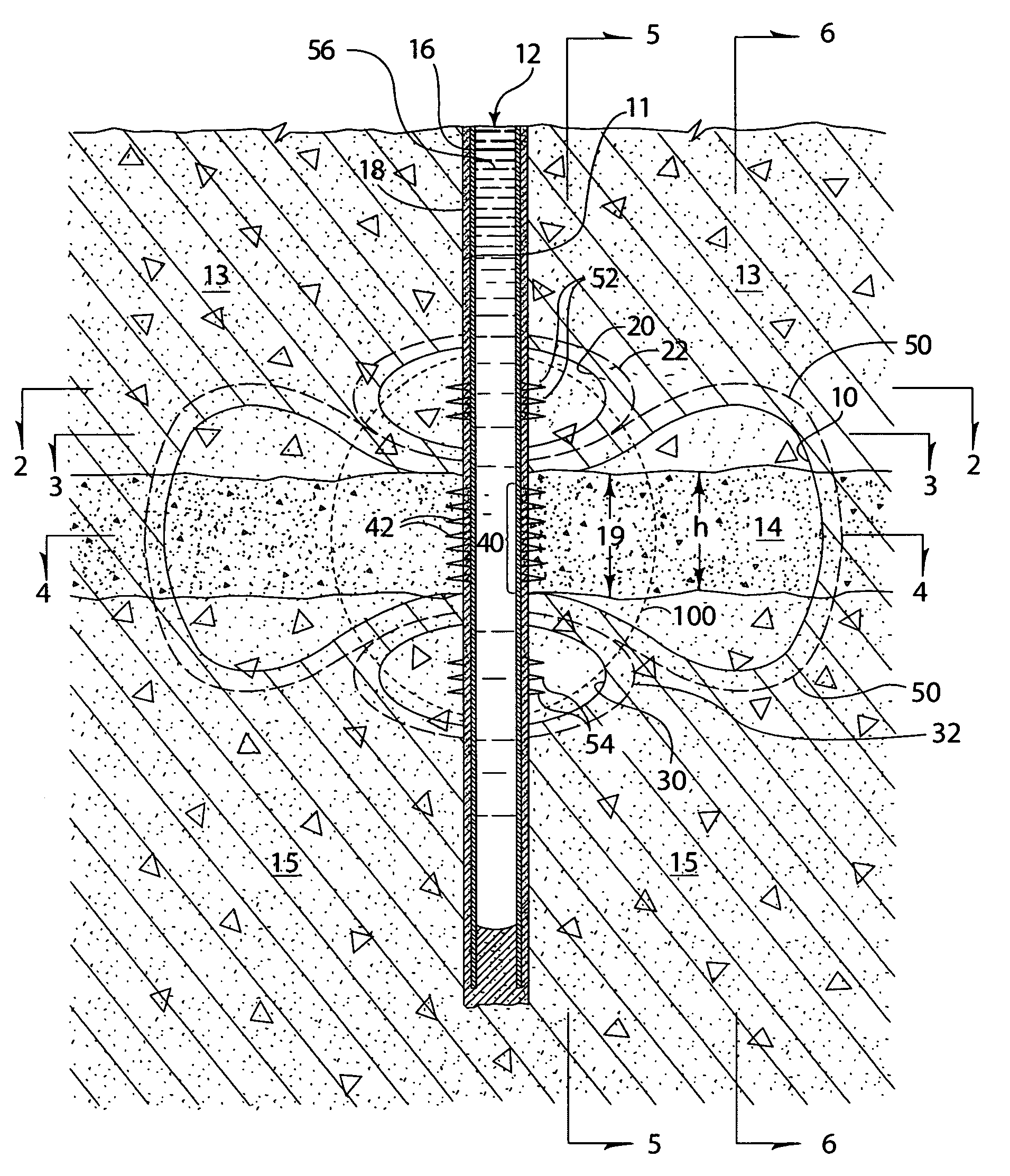
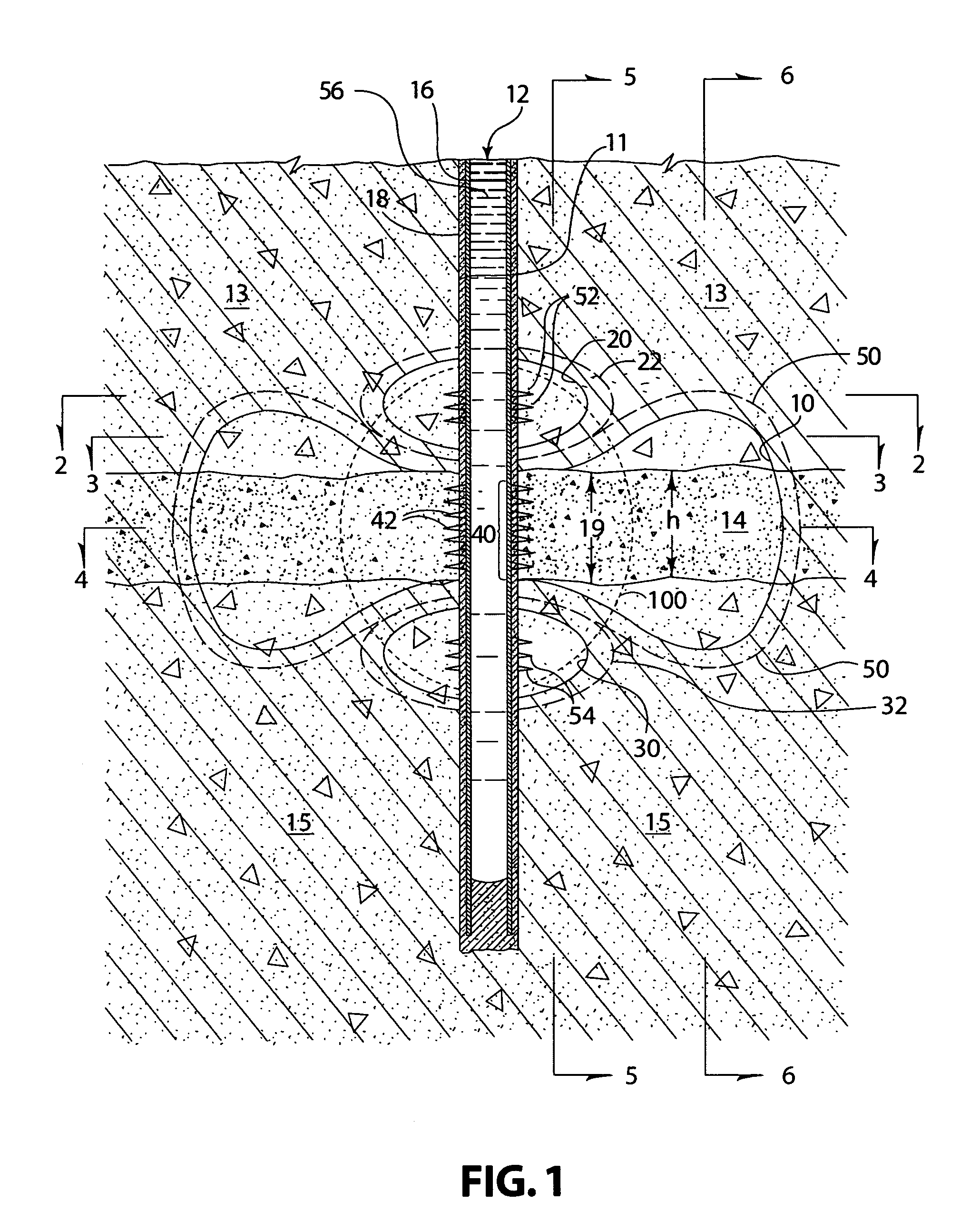
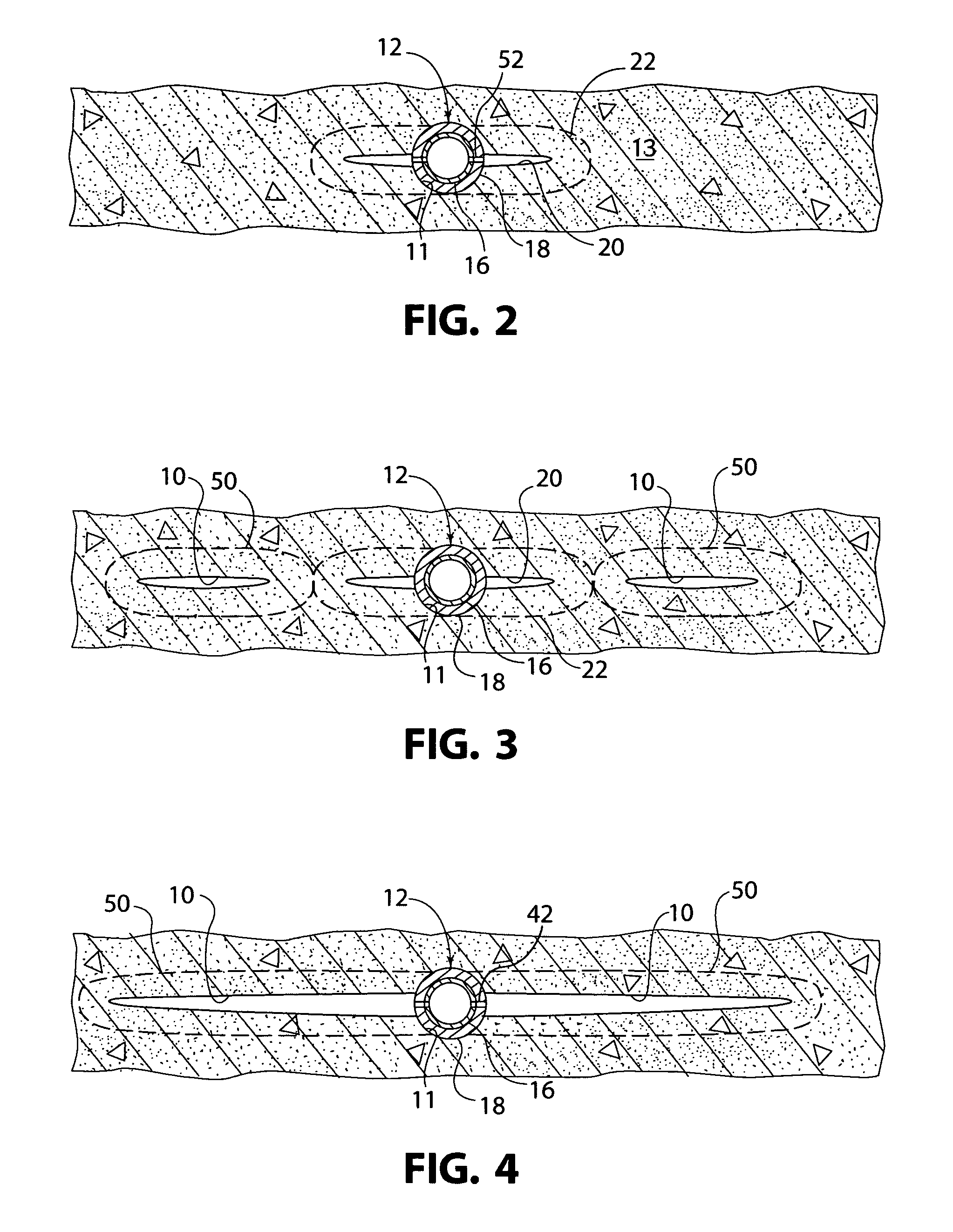
[0026]A fractured zone 10 propagated from a well 12 into a target formation 14 is illustrated diagrammatically in FIG. 1. This fractured zone 10 is sometimes referred to in this description as the “main fracture zone” or simply the “main fracture”. Of course, the relative sizes and dimensions of the main fracture zone 10, well 12, target formation 14, and other structures portrayed in FIG. 1 are not drawn to scale or to proper proportions, which would be impractical, but persons skilled in the art will understand the concepts and features illustrated in FIG. 1 and described herein. Essentially, FIG. 1 is a vertical cross-sectional view of an area around a well 12 drilled and completed into the target formation 14, with the cross-sectional view in a generally vertical plane that includes the well 12 and extends generally parallel to the maximum, naturally occurring (tectonic) compressive stress field, thus, is also co-planar with the projection of the fractured zone 10. Hydraulic fra...


PUM


Abstract

A method of propagating a fracture farther from a well-bore into an oil and/or gas-bearing zone of a target formation while inhibiting growth of the fracture into an adjacent water-bearing zone under or over the oil and/or gas-bearing zone, comprises creating a zone of increased in-situ stress a vertical distance adjacent a target interval and then creating a main fracture in the target interval by, for example, fracturing the target interval with enough fracture fluid and pressure to propagate the main fracture, inter alia, vertically to the zone of increased in-situ stress. When vertical growth of the main fracture reaches the limit set by the zone of increased stress, additional fracture fluid pumped into the target interval tends not to propagate the main fracture vertically beyond that limit and, instead, tends to propagate the main fracture more laterally and farther from the well. Such zone(s) of increased in-situ stress can be created above, below, or both above and below the target interval.

Description

RELATED PATENT APPLICATIONS[0001]This patent application claims the benefit of U.S. Provisional Application No. 60 / 432,784, filed on Dec. 12, 2002, which is incorporated herein by reference.BACKGROUND OF THE INVENTION[0002]1. Field of the Invention[0003]This invention pertains generally to fracturing of oil and gas bearing and other geological formations, and, more specifically, to a method of extending fracture geometry farther into a target formation by increasing in-situ stress in adjacent formations or in adjacent portions of the same formation.[0004]2. Brief Description of the Prior Art[0005]When wells are drilled into geological rock formations for the purpose of producing oil, gas, or water from such formations or for other purposes, such as injection of fluids into the formation, mining, and the like, hydraulic fracturing is a primary method for increasing fluid production or injection rates. In general, one way to fracture a formation is to pump a fluid down a casing or tub...

Claims


Application Information

Patent Timeline
Patent Type & Authority Patents(United States)
IPC IPC(8): E21B43/26
CPCE21B43/26
Inventor AUD, WILLIAM W.
Owner NEW IPT INC
Why Eureka
Try Eureka