Methods and apparatus for generating force and torque

a technology of generating force and torque, applied in the direction of machine supports, building scaffolds, television systems, etc., can solve the problems of high risk of inappropriate adjustment of monitor or display at one setting for one individual, high cost of gas springs and wear, and large space occupation of gas springs, etc., to achieve easy adjustment, less cost of manufacture and maintenance, and improved reliability

Inactive Publication Date: 2006-04-25
ERGOTRON
View PDF52 Cites 82 Cited by
  • Summary
  • Abstract
  • Description
  • Claims
  • Application Information

AI Technical Summary

Benefits of technology

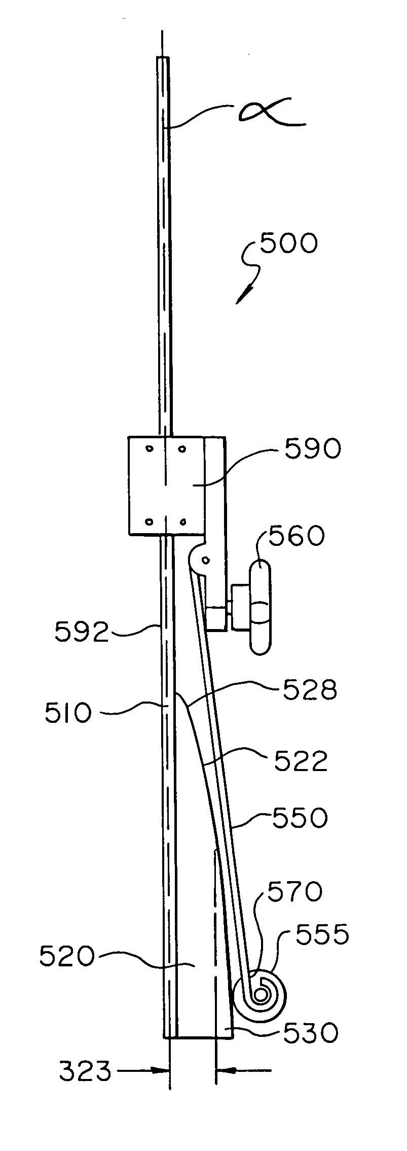
[0014]The cam following assembly may be advantageously moveable along the longitudinal axis between at least a first position and a second position. The spring advantageously has a first deflection when the cam following assembly is in the first position and a second deflection when the cam following assembly is in the second position. Also, the first roller advantageously has a first contact angle when the cam following assembly is in the first position and a second contact angle when the cam following assembly is in the second position.
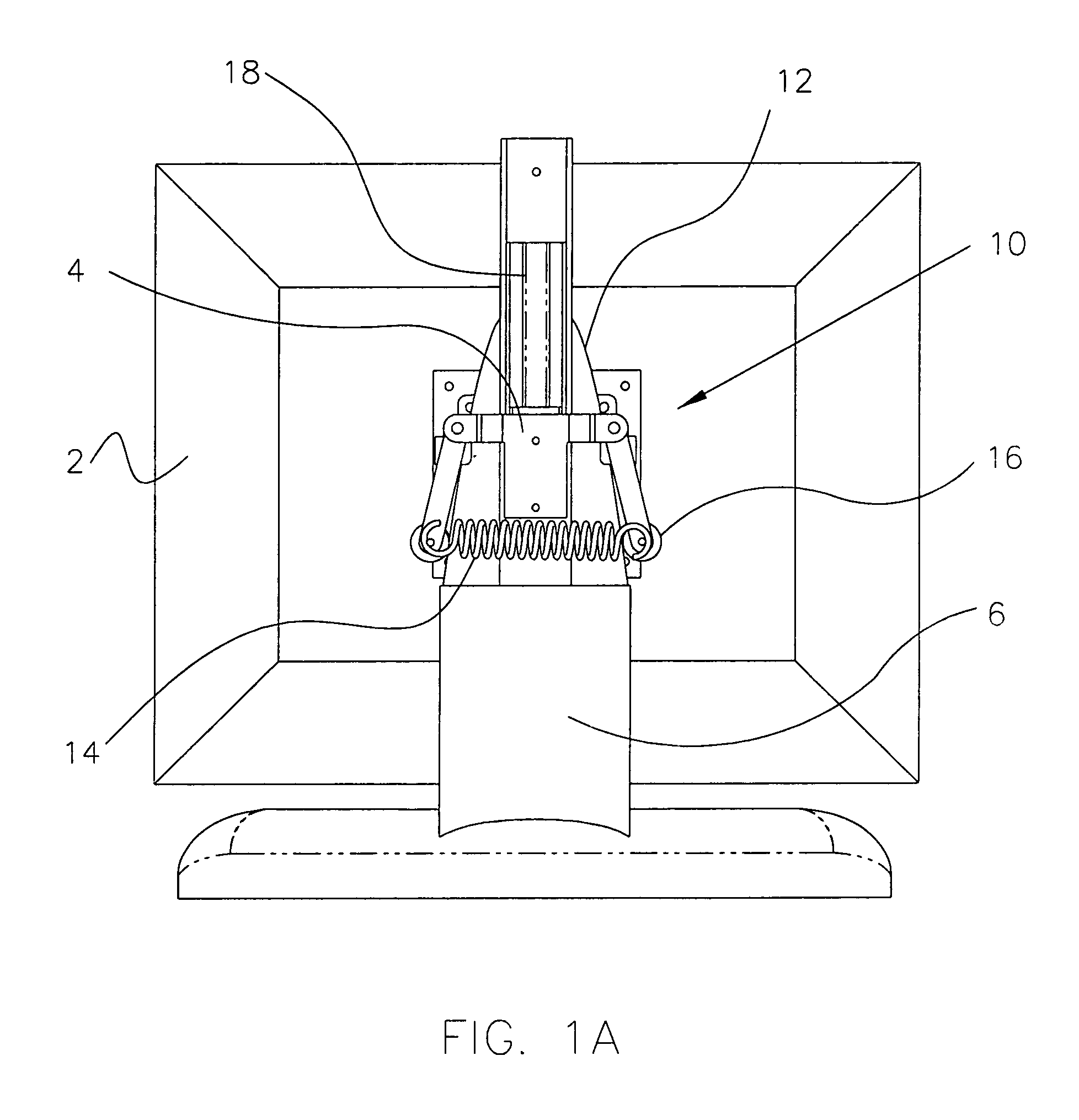
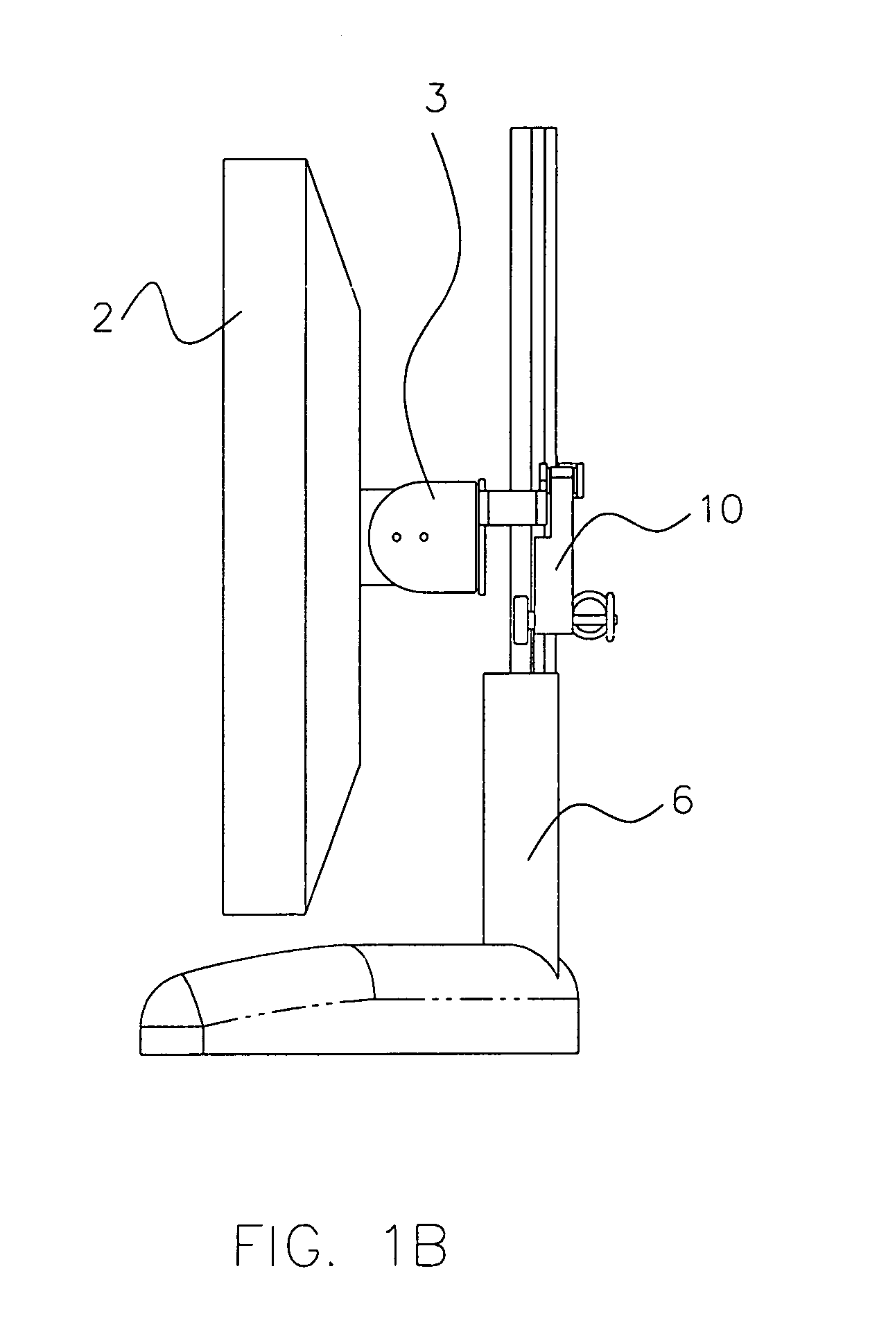
[0041]Among other advantages, the present monitor support system provides mechanisms which can be compact, scalable, have a long range of travel, and have a slim profile. In addition, the monitor support mechanisms are low cost and light weight. A further benefit is when multiple components are simultaneously secured with the same mechanism to achieve an efficient use of space and provide common movement of the components. In one embodiment, a single mechanism can be changed or adjusted to allow various weight components to be counterbalanced by the same mechanism.

Problems solved by technology

Given the differences in people's size and differences in their preferences, a monitor or display adjusted at one setting for one individual is highly likely to be inappropriate for another individual.
An operator may choose to use the monitor as left by the previous user despite the discomfort, annoyance and inconvenience experienced by a user who uses settings optimized for another individual, which may even result in injury after prolonged use.
However, the gas springs are costly and wear out over time.
In addition, the gas springs require a significant amount of space, for instance arm length, which can be at a premium in certain applications, such as in hospitals.

Method used


Image

  • Methods and apparatus for generating force and torque
  • Methods and apparatus for generating force and torque
  • Methods and apparatus for generating force and torque

Examples


Embodiment Construction

[0137]In the following detailed description, reference is made to the accompanying drawings which form a part hereof, and in which is shown by way of illustration specific embodiments in which the invention may be practiced. These embodiments are described in sufficient detail to enable those skilled in the art to practice the invention, and it is to be understood that other embodiments may be utilized and that structural changes may be made without departing from the scope of the present invention. Therefore, the following detailed description is not to be taken in a limiting sense, and the scope of the present invention is defined by the appended claims and their equivalents. In the present description, “vertical,”“horizontal,”“lateral,”“up,”“down,”“raised,”“lowered,” and the like are meant to be taken in their relative sense in regards to the position of the monitor support mechanism in the figures and the context of the description, and they are not to be taken in their absolute...


PUM


Abstract

A system for providing support and position control of a monitor. In one embodiment, a method of supporting a monitor includes converting an ascending energy storage member force curve into a substantially constant supporting force against the monitor. In one aspect, a method, of supporting a monitor includes providing an energy storage member and a cam which are cooperatively positioned so as to move relative to each other along the path of motion. As the energy storage member moves along the path relative to the cam, the cam displaces the energy storage member and thereby changes a force applied by the energy storage member on the cam, and wherein the cam converts the force applied by the energy storage member into a supporting force on the monitor.

Description

RELATED APPLICATIONS[0001]The present Application claims the benefit of U.S. Provisional Patent Application, Ser. No. 60 / 295,336, filed Jun. 1, 2001, the disclosure of which is hereby incorporated by reference herein. The present Application is also a continuation-in-part of U.S. patent application Ser. No. 09 / 724,494, filed Nov. 28, 2000, entitled MONITOR SUPPORT SYSTEM.FIELD OF THE INVENTION[0002]The present invention relates generally to an apparatus for providing a linear force and / or a rotary torque. More particularly, the present invention relates to an apparatus that may be utilized to position various devices. Examples of devices which may be suitable in some applications include basketball backboards, computer monitors, drawers, doors, and the like.BACKGROUND OF THE INVENTION[0003]The present invention relates generally to an apparatus for providing a linear force and / or a rotary torque. More particularly, the present invention relates to an apparatus that may be utilized t...

Claims


Application Information

Patent Timeline
Patent Type & Authority Patents(United States)
IPC IPC(8): A47F1/10F16M11/10F16M11/24
CPCF16M11/10F16M11/18F16M11/2014F16M11/24F16M13/022Y10S248/919F16M2200/022F16M2200/041F16M2200/045Y10S248/918H04N5/655
Inventor SWEERE, HARRY C.ALZEBDEH, KHALID I.ELIASON, JEFFERY M.SHOWALTER, MATTHEW J.LINDBLAD, SHAUN C.AHMETOGLU, MUSTAFA A.
Owner ERGOTRON
Why Eureka
Try Eureka