Projection-type display apparatus

a display apparatus and projection-type technology, applied in the field of projection-type display apparatuses, can solve the problems of reducing the quality of black display and deteriorating contrast performance, and achieve the effect of improving contrast performance and minimizing brightness reduction

Inactive Publication Date: 2006-04-25
PANASONIC CORP
View PDF28 Cites 2 Cited by
  • Summary
  • Abstract
  • Description
  • Claims
  • Application Information

AI Technical Summary

Benefits of technology

[0011]It is an object of the present invention to solve the conventional problem described above and to provide a projection-type display apparatus that improves contrast performance while avoiding shielding of necessary light so as to minimize brightness reduction.

Problems solved by technology

Since this unwanted reflection light 11 travels similarly in both times of ON / OFF signals, it considerably reduces the quality of black display especially at the time of OFF traveling, causing a deterioration of contrast performance.

Method used


Image

  • Projection-type display apparatus
  • Projection-type display apparatus
  • Projection-type display apparatus

Examples


first embodiment

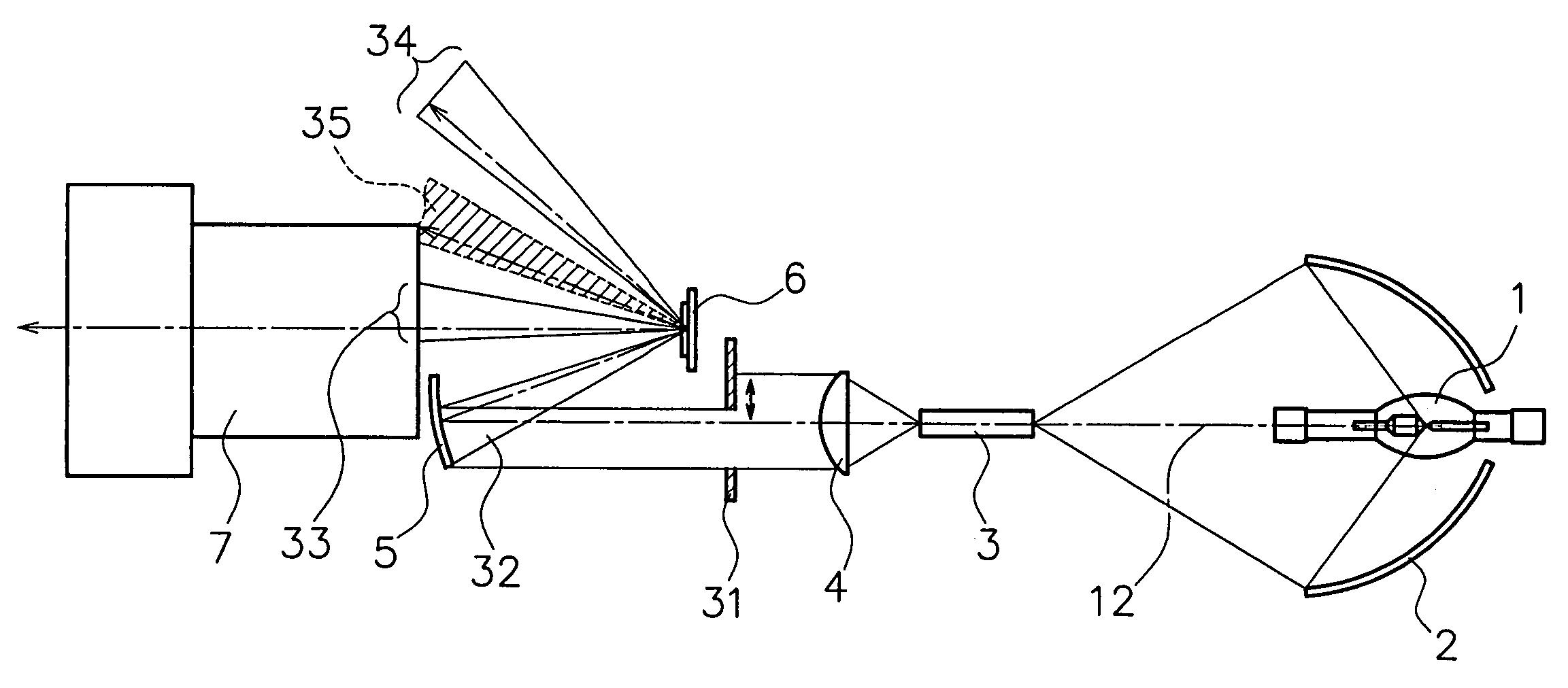
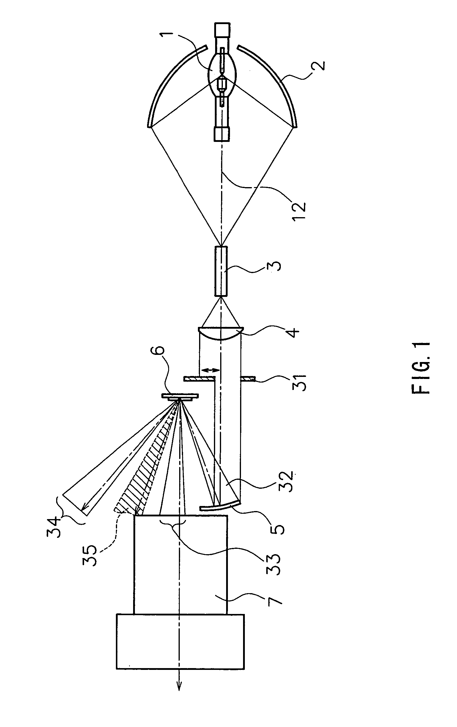
[0046]FIG. 1 shows a schematic configuration of a projection-type display apparatus according to a first embodiment of the present invention. In this figure, numeral 1 denotes a lamp serving as a light source, numeral 31 denotes a diaphragm, numeral 6 denotes a reflecting light valve, and numeral 7 denotes a projection lens. Also, an optical system constituted by a concave mirror 2, a rod prism 3, a condenser lens 4 and a focusing mirror 5 is collectively called an illuminating optical system. Numeral 12 indicates an optical axis of the illuminating optical system.

[0047]The reflecting light valve 6 serving as an image forming member has mirror elements 21 formed in a matrix pattern, each of which corresponds to a pixel, controls a traveling direction of light according to a video signal and forms an optical image by a change in a reflection angle as described referring to FIG. 10. The concave mirror 2 is an elliptical surface mirror that has a reflecting surface with an elliptical c...

second embodiment

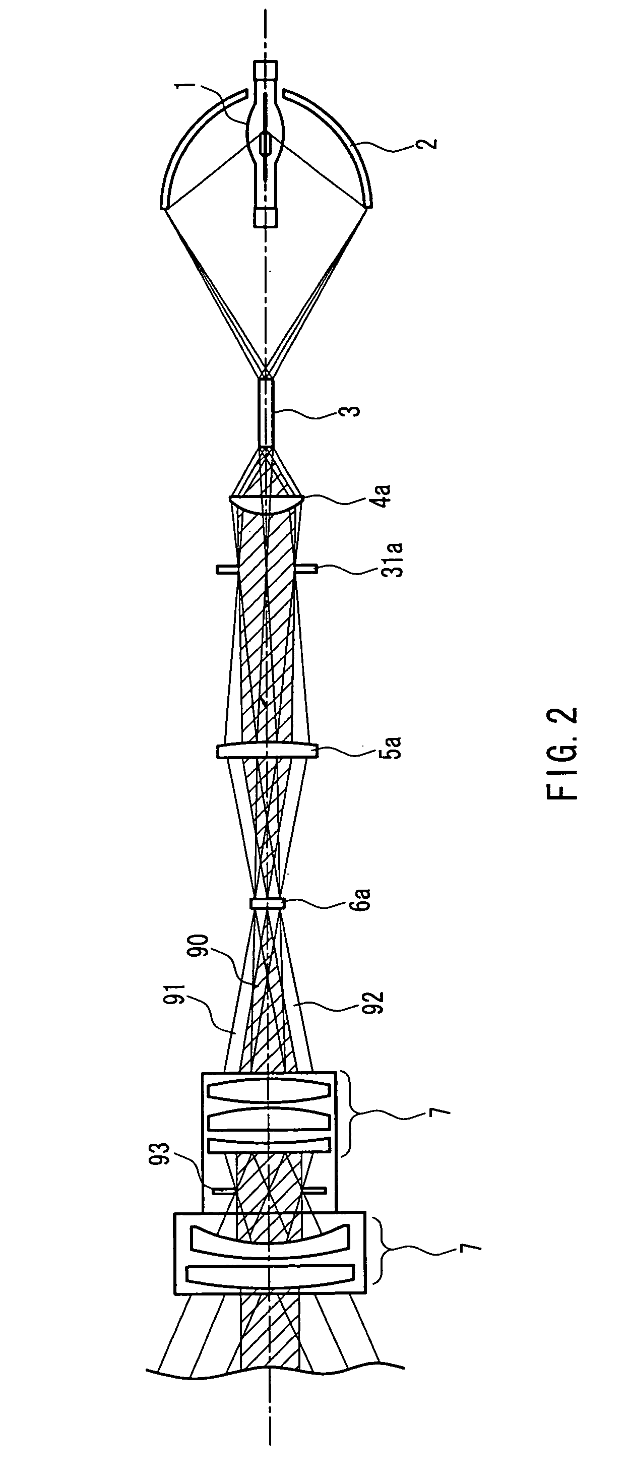
[0077]FIG. 5 shows a schematic configuration of a projection-type display apparatus according to a second embodiment of the present invention. In this figure, the lamp 1 serving as a light source, the reflecting light valve 6 and the projection lens 7 are equivalent to those shown in FIG. 1. Also, an optical system constituted by a concave mirror 2, a rod prism 3, a condenser lens 4, a reflecting mirror 42, a field lens 43 and a total reflection prism 44 is collectively called an illuminating optical system.

[0078]The concave mirror 2, the rod prism 3 and the condenser lens 4 have the same effects as in the embodiment described referring to FIG. 1, and therefore, the description thereof will be omitted. In the present embodiment, light that has left the condenser lens 4 travels via the reflecting mirror 42 and the field lens 43 and reaches the total reflection prism 44.

[0079]Here, the effect of the total reflection prism 44 will be described. The total reflection prism 44 is constitu...

third embodiment

[0087]FIG. 7 shows a schematic configuration of a projection-type display apparatus according to a third embodiment of the present invention. In this figure, the lamp 1 serving as a light source, the reflecting light valve 6 and the projection lens 7 are equivalent to those shown in FIG. 1. Also, as in FIG. 5, a system constituted by a concave mirror 2, a rod prism 3, a condenser lens 4, a reflecting mirror 42, a field lens 43 and a total reflection prism 44 is collectively called an illuminating optical system.

[0088]The concave mirror 2, the rod prism 3 and the condenser lens 4 have the same effects as in the embodiment described referring to FIG. 1, and therefore, the description thereof will be omitted. In the present embodiment, a color separation / combination prism 62 is disposed between the total reflection prism 44 and the reflecting light valve 6, and three reflecting light valves 6 are used.

[0089]In the following, the structure and effect of the color separation / combination ...


PUM

PropertyMeasurementUnit
aspect ratioaaaaaaaaaa

Abstract

An illuminating optical system for focusing a radiant light of a light source (1) onto a reflecting light valve (6) and a projection lens (7) for magnifying and projecting a reflected light from the reflecting light valve (6) onto a screen are provided, a diaphragm (31) is disposed at a substantially conjugate position of an entrance pupil of the projection lens (7) on an optical path of the illuminating optical system, the diaphragm (31) has an opening whose area is changed by a light-shielding member, and a shape of a shielded portion of the diaphragm (31) shielded by the light-shielding member is rotationally asymmetric to an optical axis (12) of the illuminating optical system. Accordingly, shielding of necessary light can be better avoided compared with a diaphragm for changing the light-shielding area in a rotationally symmetric manner, for example, a diaphragm for narrowing the opening concentrically, making it possible to improve contrast performance while minimizing brightness reduction.

Description

[0001]This application is a continuation of application Ser. No. 10 / 470,977, filed Jul. 31, 2003, which is a National Stage application of PCT / JP02 / 04013, filed Apr. 23, 2002, which applications are incorporated herein by reference.TECHNICAL FIELD[0002]The present invention generally relates to a projection-type display apparatus that magnifies an optical image formed on a light valve and projects it onto a screen.BACKGROUND ART[0003]There has been a conventionally well-known method for obtaining a large-screen image, in which an optical image corresponding to a video signal is formed on a light valve, irradiated with light, and then magnified and projected onto a screen by a projection lens. The use of a reflecting light valve as the light valve can achieve both a high resolution and a high pixel aperture ratio, making it possible to display a highly-bright projected image with highly efficient light utilization.[0004]As a conventional example, FIG. 10 illustrates a configuration o...

Claims


Application Information

Patent Timeline
Patent Type & Authority Patents(United States)
IPC IPC(8): G03B21/14G02B26/02G02B9/08G02F1/00G03B21/28G02B5/00G02B26/08G03B21/00
CPCG02B5/005G03B21/00G02B26/0833G03B21/006G03B21/005
Inventor SANNOHE, SHINYAISHINAGA, HIDEKIYOSHIKAWA, TAKAMASA
Owner PANASONIC CORP
Why Eureka
Try Eureka