
Molar tube lock

a technology of molar tube and lock, which is applied in the field of molar tube, can solve the problems of not only discomfort, but also discomfort, and the application of the necessary force to remove the end of the archwire is often quite discomforting for the patient, and not only discomfor

Inactive Publication Date: 2006-04-25
WILKERSON MICHAEL K
View PDF14 Cites 54 Cited by
  • Summary
  • Abstract
  • Description
  • Claims
  • Application Information

AI Technical Summary

Benefits of technology

[0025]The above-mentioned problem of patient discomfort is solved by the present invention wherein a molar tube according to the present invention eliminates the need to bend archwires, as is the case when using molar tubes of the prior art, and thus inherently eliminates the use of force otherwise needed to mesially withdraw a bent archwire from the tube.
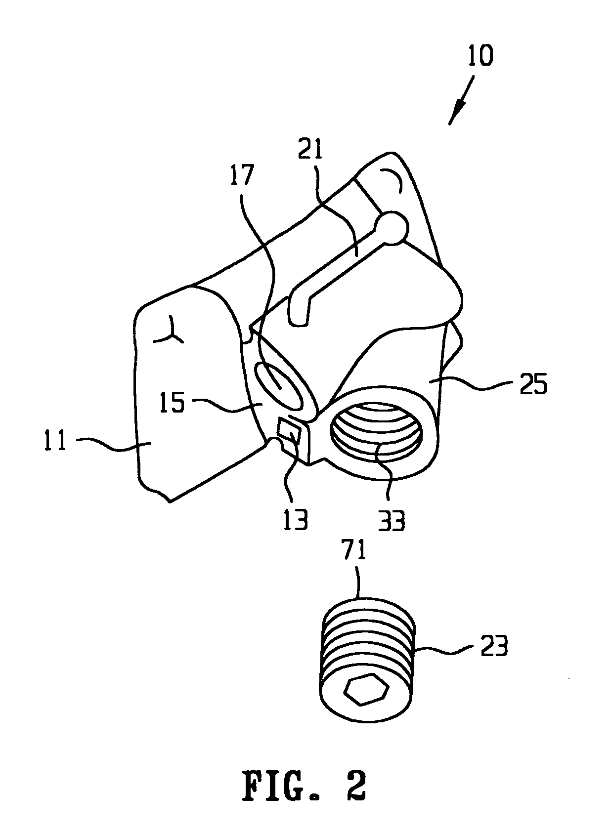
[0026]More particularly, a molar tube according to the present invention includes a lumen and a threaded boss comprising a threaded hole, wherein the axis of the threaded hole in the boss is disposed at an angle of approximately 45° to the axis of the lumen. Such an arrangement allows for the selective securing of an archwire at a desired position / tension within the lumen, while providing control over labiolingual and occlusogingival archwire movement for either round and rectangular archwires, and also torque control for rectangular archwires. Under such an arrangement, the force required to mesially withdraw a bent archwire through the tube is dramatically reduced, if not wholly eliminated in most cases.
[0027]The amount of initial force to draw the bent end of an archwire into the molar tube of the present invention and the subsequent force thereafter required to pull the archwire the full length of the tube and remove it from the tube may be reduced to a level of about 0 to 5 percent of what would normally be required with a conventional molar tube. This force reduction translates into enhanced patient comfort.

Problems solved by technology

Inasmuch as it is difficult, if not impossible, to completely straighten the ends of the wires, considerable forces are required to withdraw or pull the wires through the tubes.
The application of the necessary forces to remove archwires having bent ends is often quite discomforting to the patient.
It not only is discomforting by the force required but also because of the duration of that force as the archwire is pulled through the entire length of the tube.
Even where the bent end of an archwire used in conjunction with prior art molar tubes is attempted to be straightened in the mouth, it is virtually impossible to completely straighten the wire, and therefore withdrawal of such an archwire from a tube requires the application of some force to the tube on withdrawal.
That force, as applied to the tooth, results in discomfort to the patient.

Method used


Image

  • Molar tube lock
  • Molar tube lock
  • Molar tube lock

Examples


Embodiment Construction

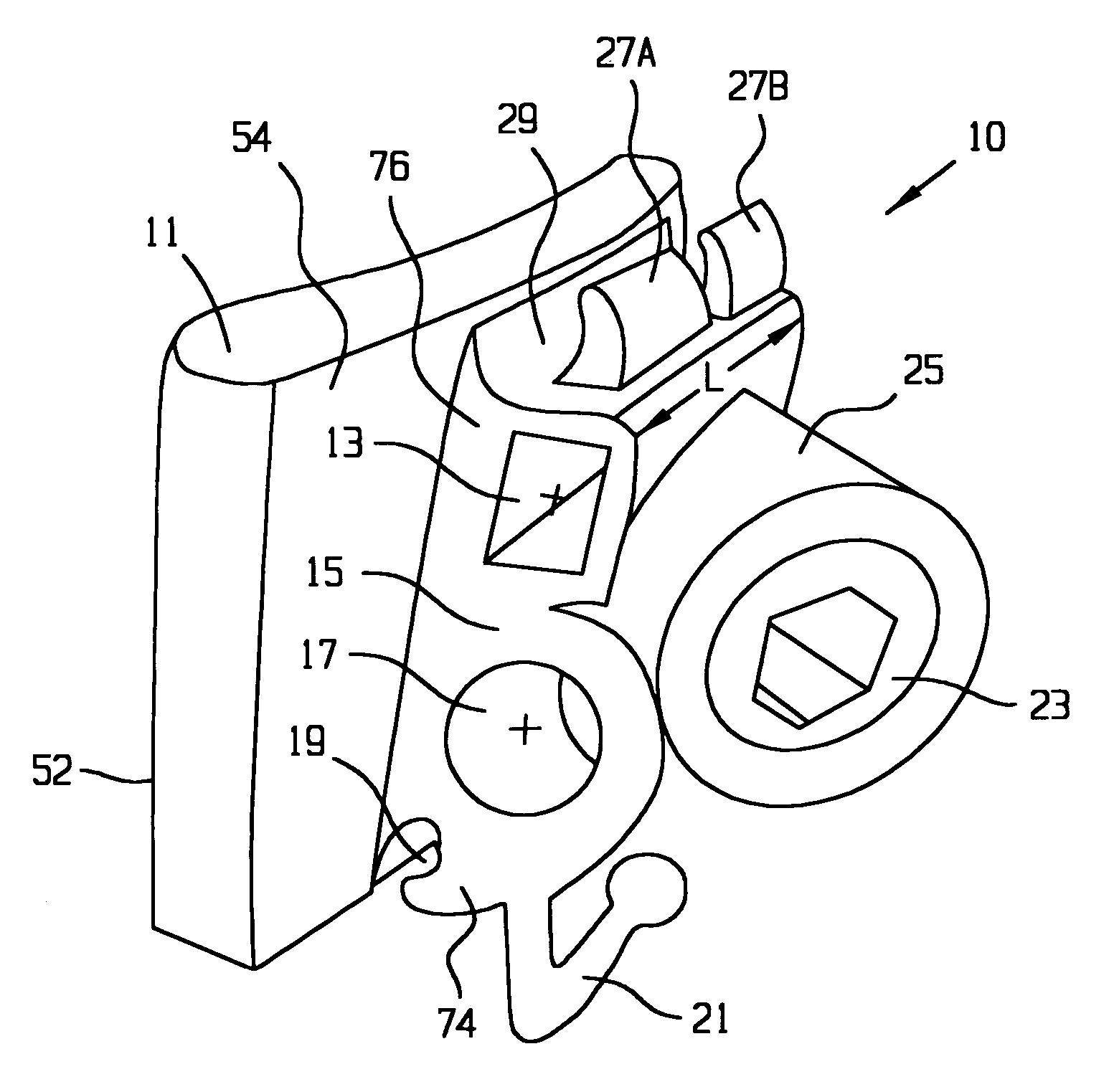
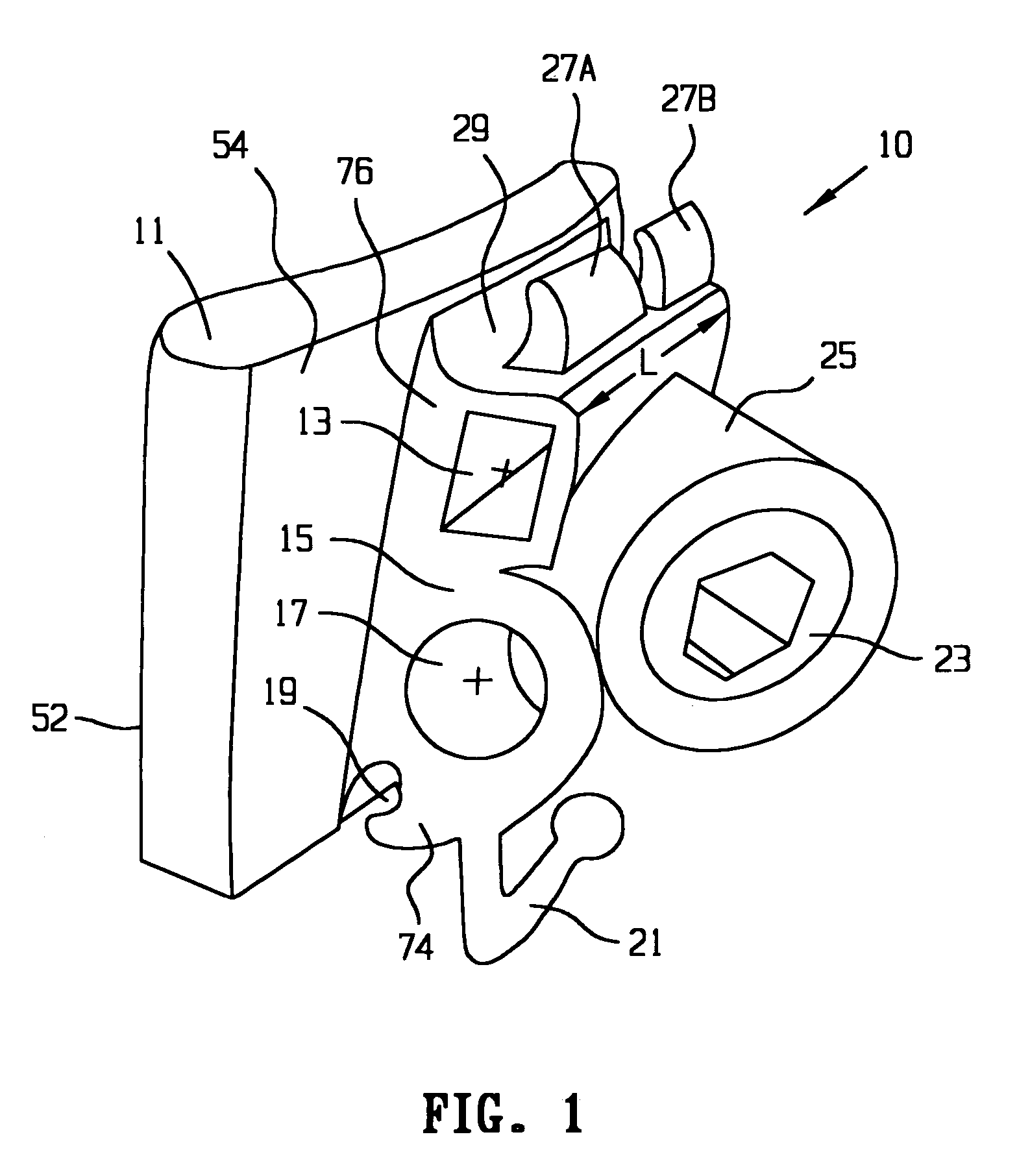
[0038]Referring to the drawings and initially to FIG. 1, there is shown a molar tube 10 according to the present invention. Such molar tube comprises a base portion 11 having a first face portion 52 and a second face portion 54. The base portion 11 is preferably fabricated according to an orthodontic prescription to deliver the correct tip and tongue features when it is subsequently properly secured to the tooth. The first face portion 52 is that surface which may to be bonded to the buccal side face of a molar tooth, using conventional dental bonding materials and methods known in the art as useful for bonding molar tubes to teeth. Typically, the face portion 52 is welded or soldered to a band that is then cemented to the molar teeth, as is known in the art; however, direct bonding is also acceptable. Disposed on the second face portion 54 is a body portion 15 that incorporates the essential features of the invention.

[0039]One essential feature of the invention is a lumen 17 that i...


PUM


Abstract

A molar tube having a first face portion that is adapted to be adhered to a molar tooth, a second face portion, and a mesial-distal length dimension. There is a body portion disposed on the second face portion of the base portion, and the body portion comprises an upper portion and a lower portion. The body portion further comprises a lumen that is adapted to receive an archwire, wherein the lumen has an axis which substantially coincides with the mesial-distal length dimension of the base portion. The body portion further comprises a boss comprising a threaded bore that is adapted to receive a setscrew, wherein the threaded bore has an axis. The axis of the threaded bore intersects with the mesial-distal length dimension to form an angle of any degree between 15 degrees and 55 degrees, including every degree therebetween. A molar tube according to the invention allows for easy adjustment of the tension in an archwire used in an orthodontic dental treatment, and provides for the painless withdrawal of the archwire at any time during or following the treatment.

Description

CROSS-REFERENCES TO RELATED APPLICATIONS[0001]This application is a Continuation-In-Part of U.S. patent application Ser. No. 10 / 091,089 filed on Mar. 6, 2002, now U.S. Pat. No. 6,733,287, the entire contents of which are herein incorporated fully by reference thereto.TECHNICAL FIELD[0002]The present invention relates generally to a molar tube, and more particularly to a molar tube that is adapted to receive an archwire. More particularly still, the invention relates to a molar tube that facilitates the withdrawal or adjustment of an archwire after the archwire has been employed in an orthodontic treatment. The invention allows an archwire to be locked in the molar tube, thus preventing slippage.BACKGROUND[0003]During orthodontic treatment and the use of fixed appliances on the teeth, including brackets for receiving an archwire, molar tubes are employed to anchor the distal ends of the archwire. The molar tubes are mounted on molar teeth, which constitute the posterior teeth in the ...

Claims


Application Information

Patent Timeline
IPC IPC(8): A61C3/00A61C7/22A61C7/28
CPCA61C7/282A61C7/22
Inventor WILKERSON, MICHAEL K.
Owner WILKERSON MICHAEL K
Learn More