
Intravascular filter retrieval device and method

a filter and intravascular technology, applied in the field of filters, can solve the problems of pulmonary embolism that can be fatal, patients are constantly at risk of a clot breaking free, and blockage of pulmonary arteries, and achieve the effect of preventing the migration of the thrombosis filter

Inactive Publication Date: 2006-04-25
LIFESCREEN SCI
View PDF20 Cites 111 Cited by
  • Summary
  • Abstract
  • Description
  • Claims
  • Application Information

AI Technical Summary

Benefits of technology

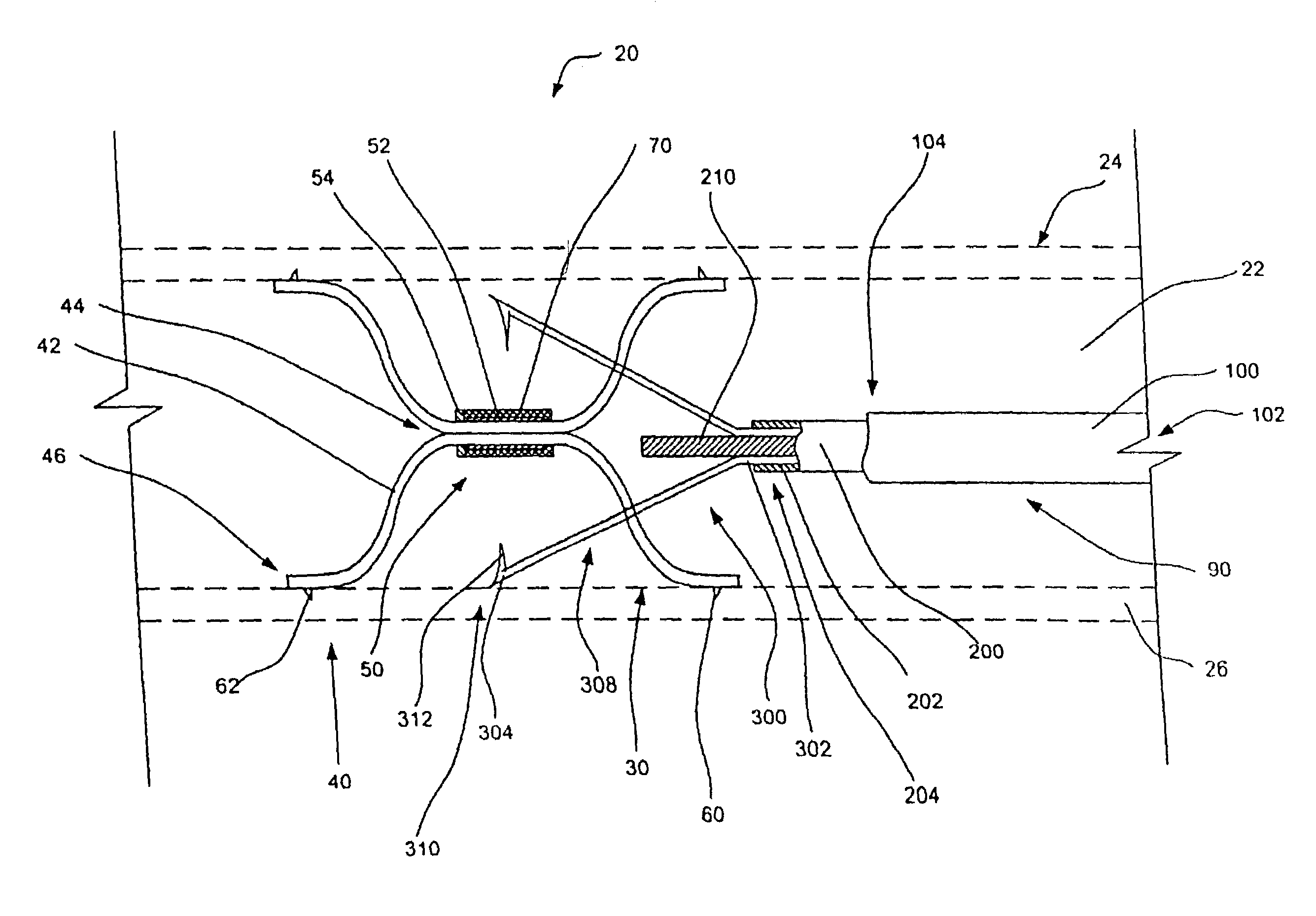
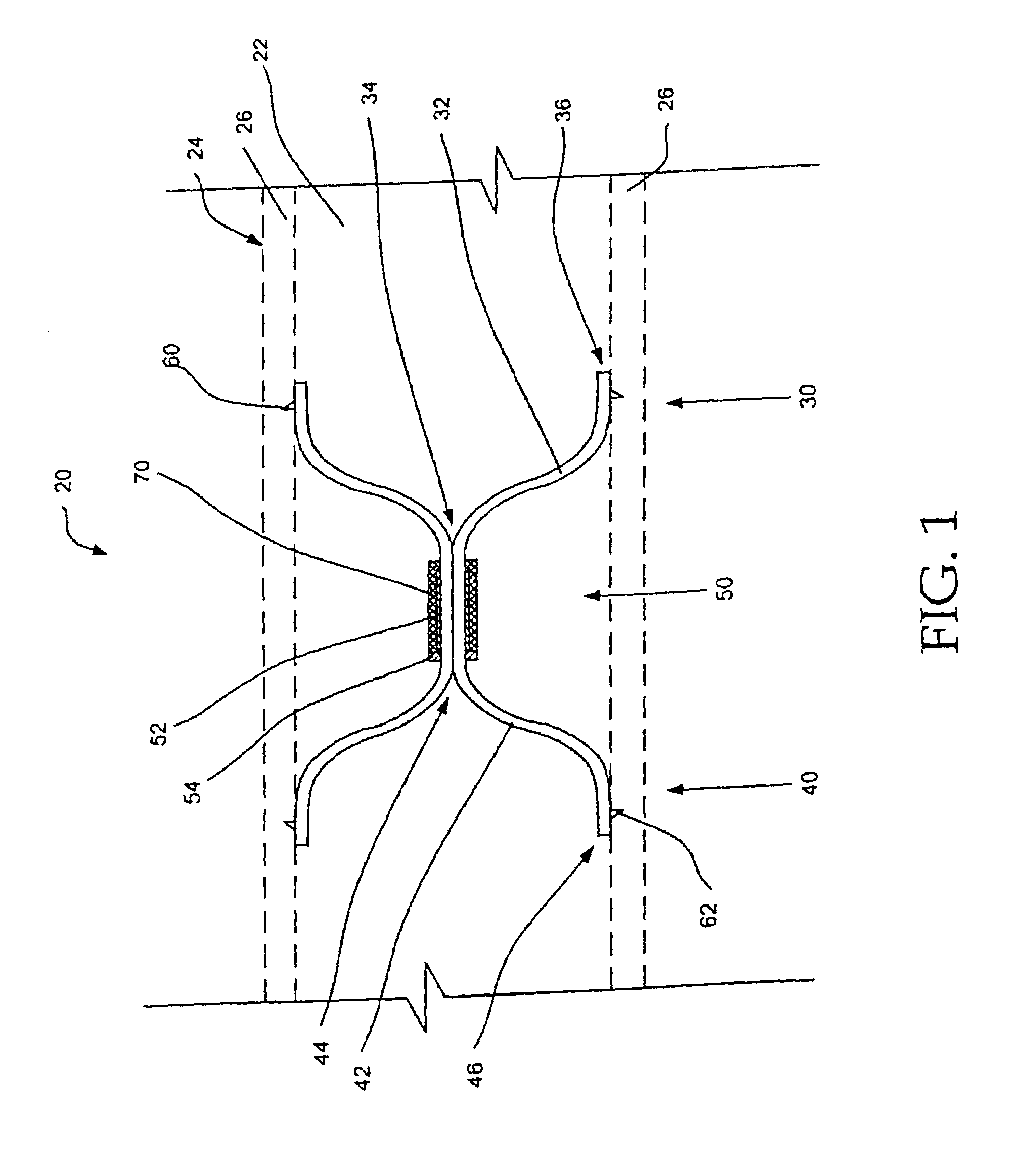
[0011]The free ends of the strands act as opposing wall contacting members and serve to position the thrombus filter in the center of a blood vessel lumen. In a presently preferred embodiment, the strands are biased to spring outward. The radial force applied to the walls of the blood vessel by the strand formations assists in preventing migration of the thrombus filter within the blood vessel lumen. The generally opposed orientation of the first strand formation relative to the second strand formation also makes migration of the filter less likely. Migration of the thrombus filter within a blood vessel lumen may also be made less likely by the inclusion of an anchor member proximate the free end of each strand.
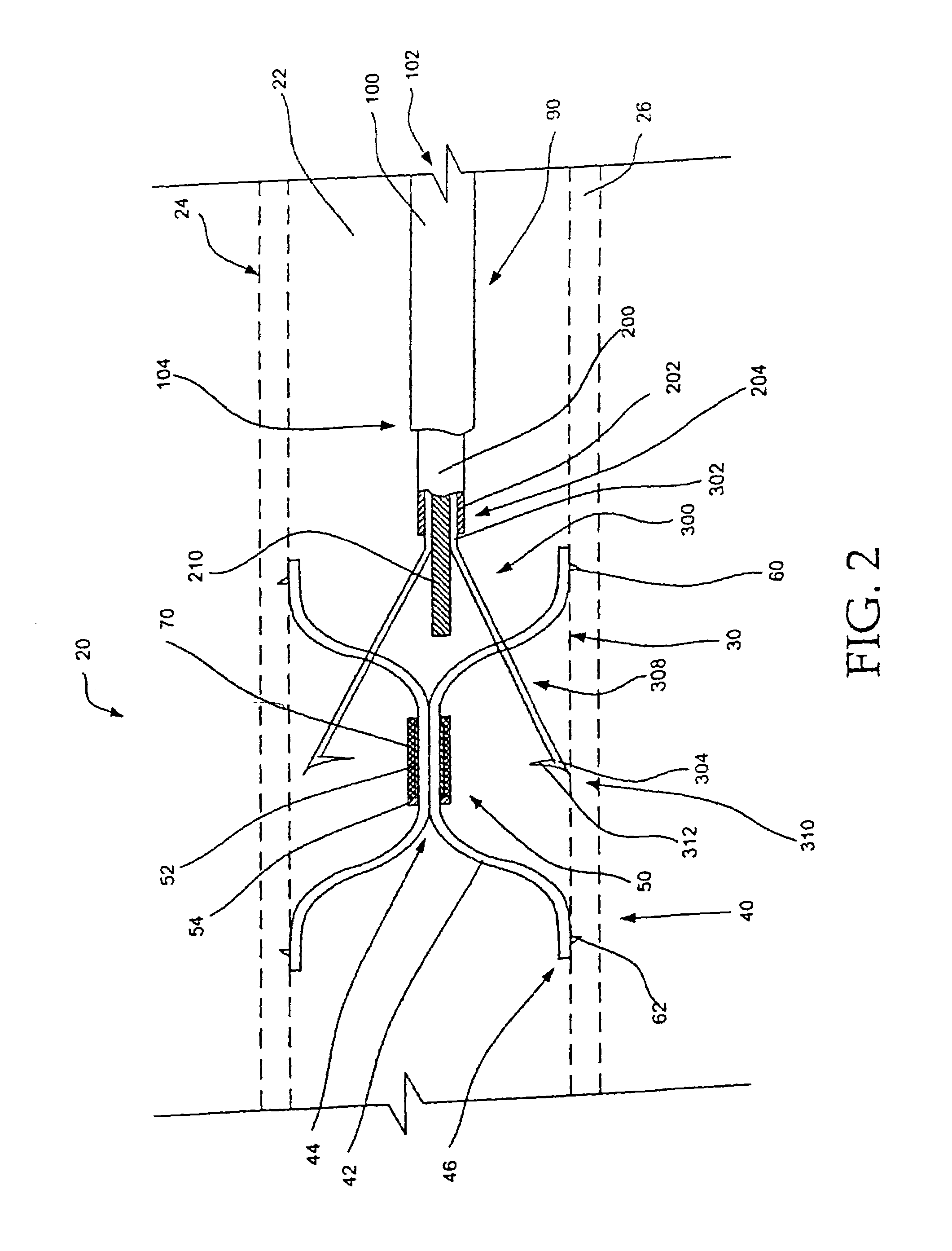
[0017]With one of the strand formations positioned within the lumen of the retrieval catheter, the remainder of the thrombus filter may also be urged into the lumen of the retrieval catheter. As described previously, the strands of the second strand formation radiate away from the joined portion of the thrombus filter in a generally opposed direction relative to the strands of the first strand formation. The orientation of the strands allows them to be pulled out of the walls of the blood vessel with minimal force. The strands of the second strand formation may be collapsed by simultaneously pushing on the proximal end of the retrieval catheter and pulling on the proximal ends of the struts.

Problems solved by technology

These patients are constantly at risk of a clot breaking free and traveling via the inferior vena cava to the heart and lungs.
Pulmonary embolization can frequently be fatal, for example when a large blood clot interferes with the life-sustaining pumping action of the heart.
If a blood clot passes through the heart it will be pumped into the lungs and may cause a blockage in the pulmonary arteries.
A blockage of this type in the lungs will interfere with the oxygenation of the blood causing shock or death.

Method used


Image

  • Intravascular filter retrieval device and method
  • Intravascular filter retrieval device and method
  • Intravascular filter retrieval device and method

Examples


Embodiment Construction

[0024]The following detailed description should be read with reference to the drawings, in which like elements in different drawings are numbered identically. The drawings which are not necessarily to scale, depict selected embodiments and are not intended to limit the scope of the invention.

[0025]Examples of constructions, materials, dimensions, and manufacturing processes are provided for selected elements. All other elements employ that which is known to those of skill in the field of the invention. Those skilled in the art will recognize that many of the examples provided have suitable alternatives which may be utilized.

[0026]Reference is now made to the drawings, in which like numbers refer to like elements throughout. FIG. 1 is a plan view of a thrombus filter 20 positioned in a lumen 22 of a blood vessel 24. Blood vessel 24 includes walls 26 which define lumen 22. The main components of thrombus filter 20 are a first strand formation 30, second strand formation 40, and a join...


PUM


Abstract

A thrombus filter configured for placement in within a blood vessel lumen defined by a blood vessel wall. Methods and devices for selectively removing the thrombus filter when the presence of a filter in the vascular system is no longer desired. The thrombus filter includes a first strand formation, a second strand formation, and a joined portion.

Description

[0001]This application is a continuation of Ser. No. 09 / 863,660 filed May 22, 2001 now U.S. Pat. No. 6,558,404 which is a continuation of Ser. No. 09 / 388,563 filed Sep. 2, 1999 now U.S. Pat. No. 6,251,122.FIELD OF THE INVENTION[0002]The present invention relates generally to filters for use inside blood vessels. More particularly, the present invention relates to thrombus filters which can be securely adjoined at a selected location in the vascular system and selectively removed when the presence of a filter in the vascular system is no longer desired.BACKGROUND OF THE INVENTION[0003]There are a number of situations in the practice of medicine when it becomes desirable for a physician to place a filter in the vascular system of a patient. One of the most common applications for vascular filters is the treatment of Deep Venous Thrombosis (DVT). Deep Venous Thrombosis patients experience clotting of blood in the large veins of the lower portions of the body. These patients are constan...

Claims


Application Information

Patent Timeline
IPC IPC(8): A61M29/00A61B17/00A61B17/50A61F2/01
CPCA61F2/01A61F2002/011A61F2230/0078A61F2230/005A61F2002/016A61F2/011A61F2/0105A61F2/012
Inventor TSUKERNIK, VLADIMIR
Owner LIFESCREEN SCI
Learn More