Direct resistance measurement corrosion probe

a corrosion probe and direct resistance technology, applied in weather/light/corrosion resistance, resistance/reactance/impedence, instruments, etc., can solve problems such as widespread systemic damage or failure, affecting the health and safety of individuals operating the system, and affecting the corrosion of pipes and vessels

Inactive Publication Date: 2006-04-25
GILBOE DEREK
View PDF26 Cites 128 Cited by
  • Summary
  • Abstract
  • Description
  • Claims
  • Application Information

AI Technical Summary

Problems solved by technology

In industrial and process environments the corrosion of pipes and vessels poses a major concern.
System failure due to corrosion can result in extensive downtime, can result in widespread systemic damage or failure, and can endanger the health and safety of individuals operating the system.
There are a number of problems associated with the existing probes.
The use of ratiometric measurement to compare a corroding element with a reference element is limited in accuracy and resolution.
Current probes do not integrate electronics and memory and rely on transmitting readings to an external analysis and storage system by means of cables or wires.
The remote nature of the electronics and memory components results in undesired effects that reduce the precision of the readings obtained from the exposed metal element.
The remote electronics and memory components increase the complexity and cost of the corrosion detection system and can often be impractical to utilize in the industrial or field setting.
Further, with existing probes, integral temperature compensation must be conducted which increases the complexity of accurate data interpretation.
This problem is amplified by the introduction of additional thermal effects due to the manufacturing processes utilized.
Also the data obtained from current probes is often difficult to read and interpret or reproduce.

Method used


Image

  • Direct resistance measurement corrosion probe
  • Direct resistance measurement corrosion probe
  • Direct resistance measurement corrosion probe

Examples


Embodiment Construction

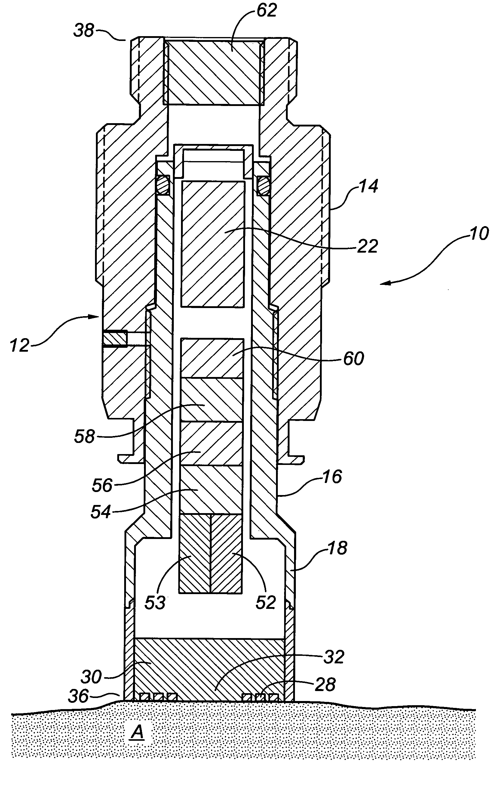
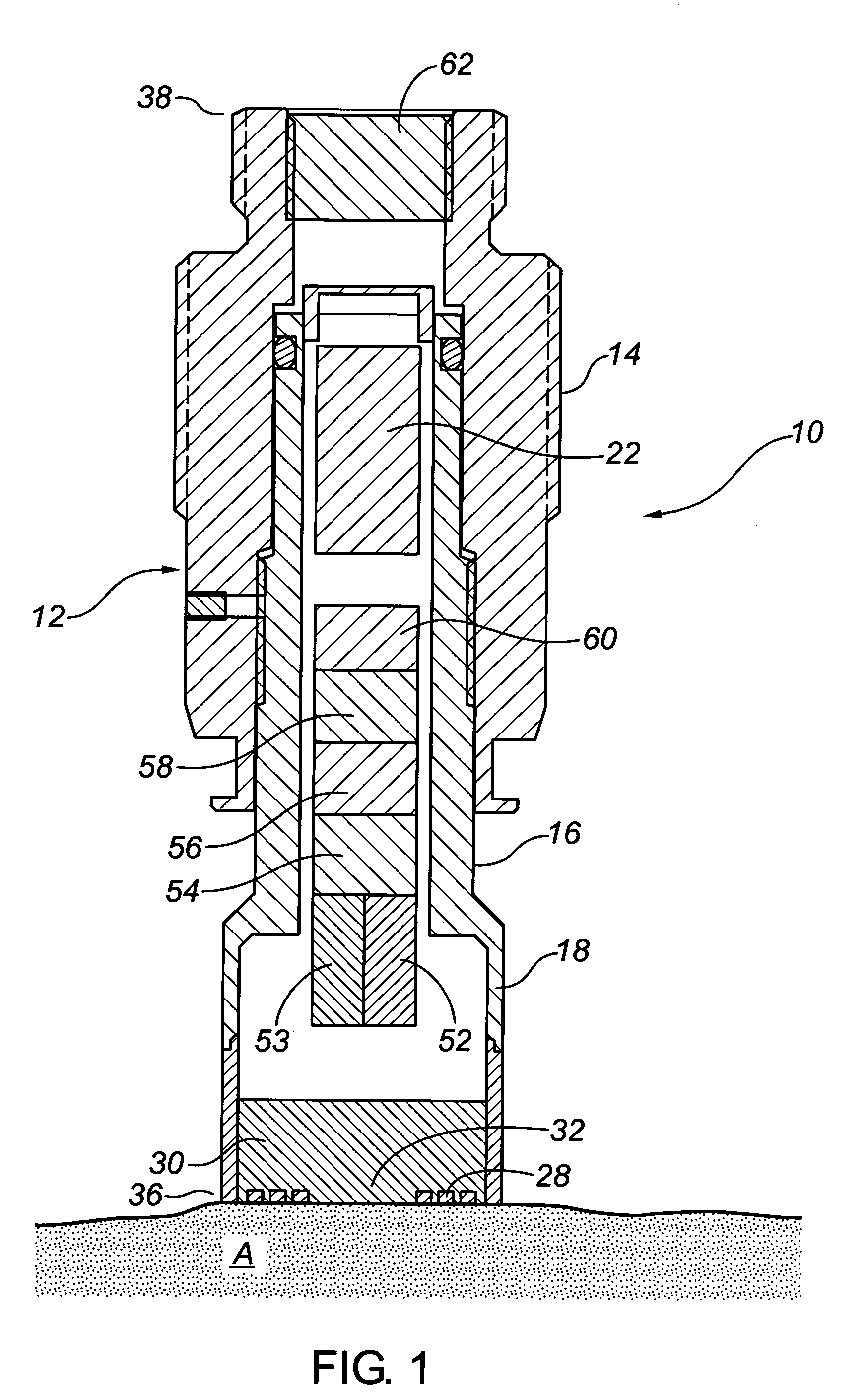
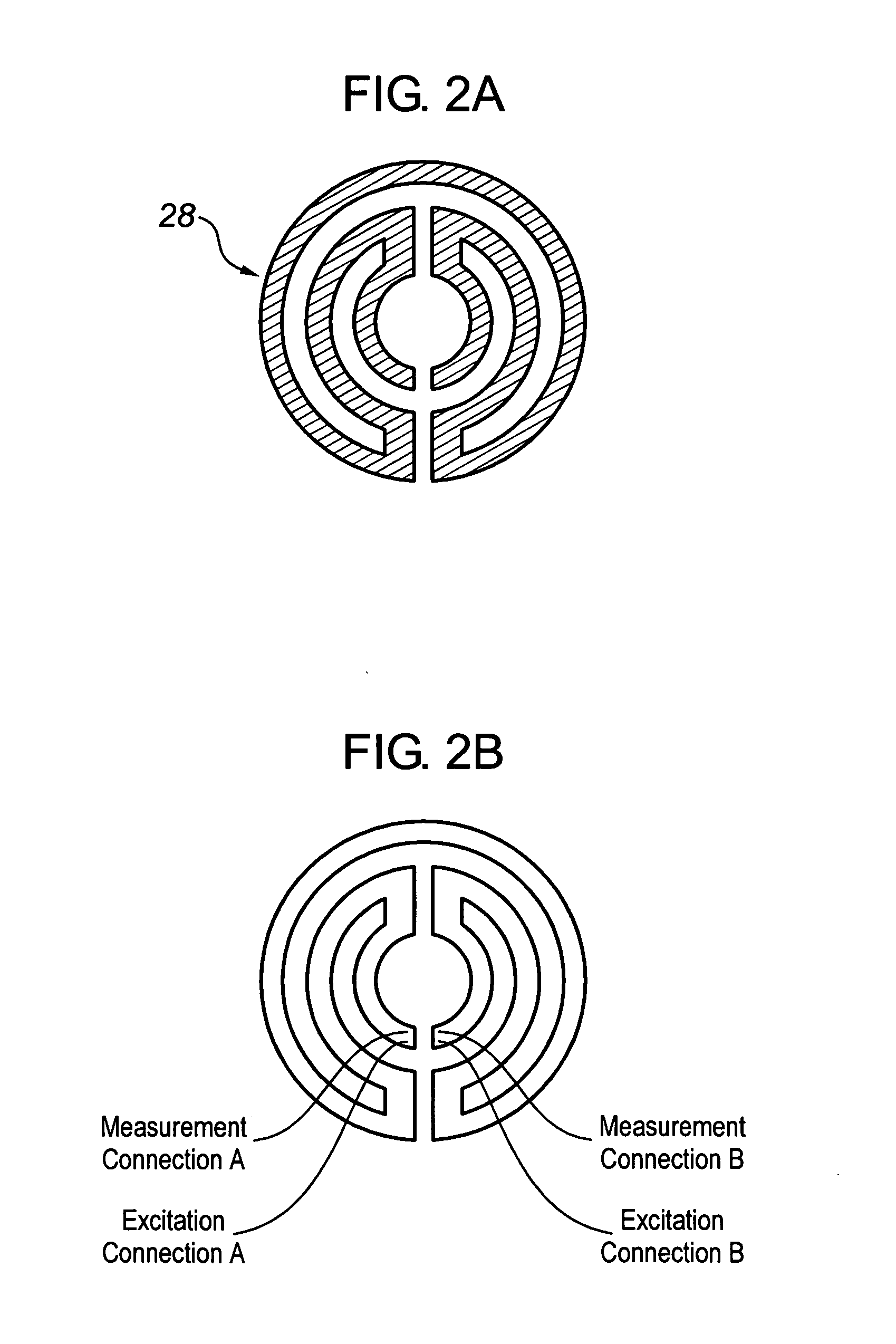
[0025]The present invention relates to a probe for monitoring corrosion in a pipe or vessel. The probe directly measures electrical resistivity of an element, which may be correlated to metal loss of the element. For the purposes of the patent application the following words shall the following meanings: The “environment” means either an erosive or corrosive environment that may be causing metal loss of its containing surfaces. In one example, the environment may be the internal cavity of a pipe through which a process fluid or gas travels or a vessel containing fluid or gas. The metal loss may be occurring on the interior pipe walls. In another example, the environment may be the borehole of an oil and gas well; the metal loss may be occurring on the inner surfaces of the well tubing.

[0026]The probe (10) may be used in any environment where metal loss is a concern, including oil and gas wells, production and transmission facilities or industrial process settings. Before describing ...


PUM

PropertyMeasurementUnit
thicknessaaaaaaaaaa
thicknessaaaaaaaaaa
thicknessaaaaaaaaaa

Abstract

A direct resistance measurement probe for measuring corrosion levels and material loss. The probe includes a hollow body having a resistive element at one end that is exposed to the environment. The probe can have an internal or external power source that is electrically connected to the resistive element. A meter measures the electrical resistance of the resistive element providing data from which corrosion rates may be ascertained. A temperature sensing device measures the temperature of the resistive element. A pressure sensing device measures the pressure of the environment that the resistive element is subjected to. The probe does not use a comparative or ratiometric reference element.

Description

BACKGROUND OF INVENTION[0001]The present invention relates to an apparatus for measuring metal loss in industrial process and downhole environments. In particular, the present invention relates to a probe which permits direct measurement of electrical resistance which can provide an estimation of the metal loss at the surface of industrial or process equipment.[0002]In industrial and process environments the corrosion of pipes and vessels poses a major concern. System failure due to corrosion can result in extensive downtime, can result in widespread systemic damage or failure, and can endanger the health and safety of individuals operating the system. Therefore it is beneficial to accurately monitor corrosion and degradation rates to facilitate the replacement or repair of weakened pipes or vessels before structural failure is experienced.[0003]Probes that assess corrosion levels by measuring electrical resistance are well known. Commonly, the probe is comprised of a metal element ...

Claims


Application Information

Patent Timeline
Patent Type & Authority Patents(United States)
IPC IPC(8): G01R27/08G01N17/04G01N27/04
CPCG01N27/041G01N17/04
Inventor GILBOE, DEREK
Owner GILBOE DEREK
Why Eureka
Try Eureka