
Startup circuit for converter with pre-biased load

a technology of pre-biased load and start-up circuit, which is applied in the direction of electric variable regulation, process and machine control, instruments, etc., can solve the problems of downstream integrated circuits (ics) latching up and failing, large potentially damaging transient currents, and catastrophic failures

Inactive Publication Date: 2006-04-25
INTERSIL INC
View PDF1 Cites 81 Cited by
  • Summary
  • Abstract
  • Description
  • Claims
  • Application Information

AI Technical Summary

Benefits of technology

The solution effectively reduces startup surge currents and output voltage non-monotonicities, preventing component stress and ensuring stable operation during pre-charged load startups.

Problems solved by technology

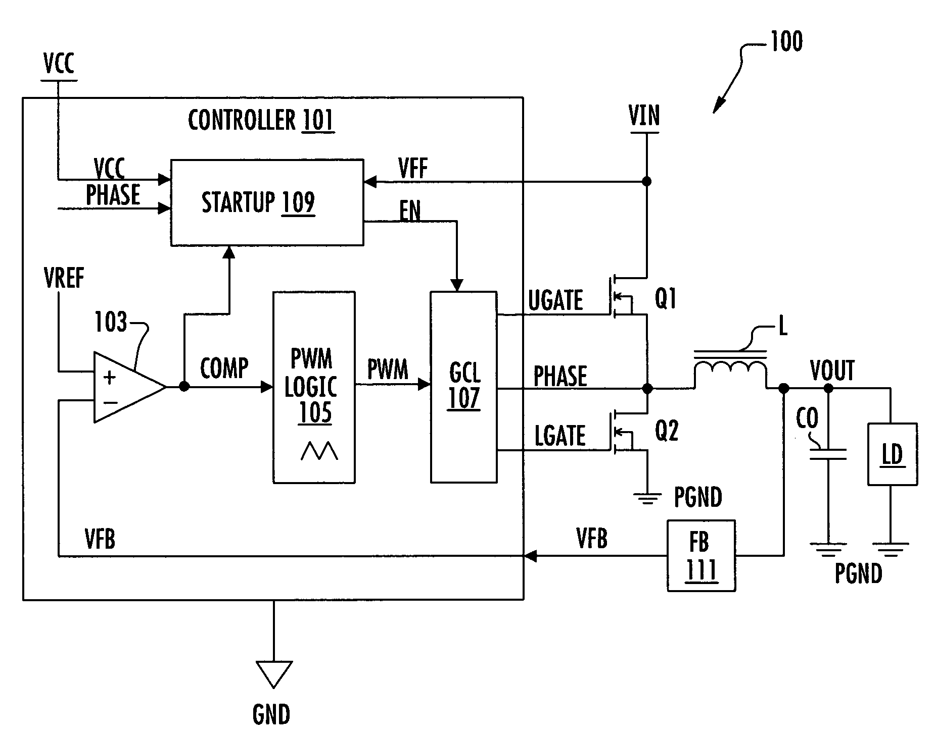
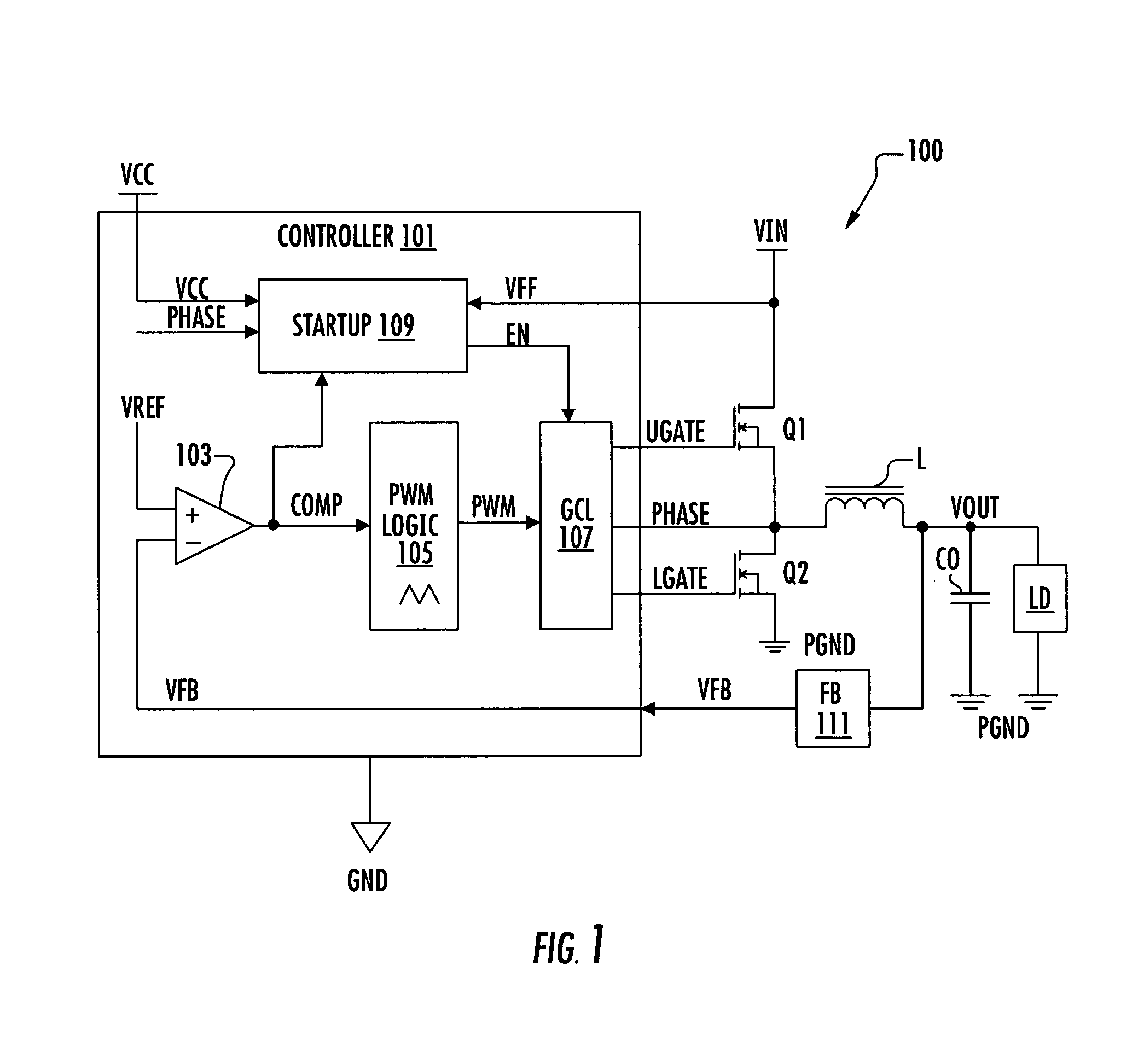
If the converter is started into a pre-baised load, such as when VOUT is already charged, there can be large potentially damaging tranisient currents because VREF is less than the feedback signal.
The surge currents can cause significant stress to on-chip components possibly resulting in catastrophic failure.
In addition, these surge currents cause “non-monotinicities” or variations in the output voltage which in some cases can cause downstream integrated circuits (ICs) to latch up and fail.

Method used


Image

  • Startup circuit for converter with pre-biased load
  • Startup circuit for converter with pre-biased load
  • Startup circuit for converter with pre-biased load

Examples


Embodiment Construction

[0025]The following description is presented to enable one of ordinary skill in the art to make and use the present invention as provided within the context of a particular application and its requirements. Various modifications to the preferred embodiment will, however, be apparent to one skilled in the art, and the general principles defined herein may be applied to other embodiments. Therefore, the present invention is not intended to be limited to the particular embodiments shown and described herein, but is to be accorded the widest scope consistent with the principles and novel features herein disclosed.

[0026]Newer methodologies, such as presented in the related disclosure entitled “STARTUP CIRCUIT FOR A DC—DC CONVERTER”, Ser. No. 10 / 775,560, reduce startup surge currents by activating the output drive of the regulator when the first driver pulse is detected, or when the compensation pin “COMP” reaches a fixed level, typically equivalent to a duty cycle (D) of about 10%. Surge...


PUM


Abstract

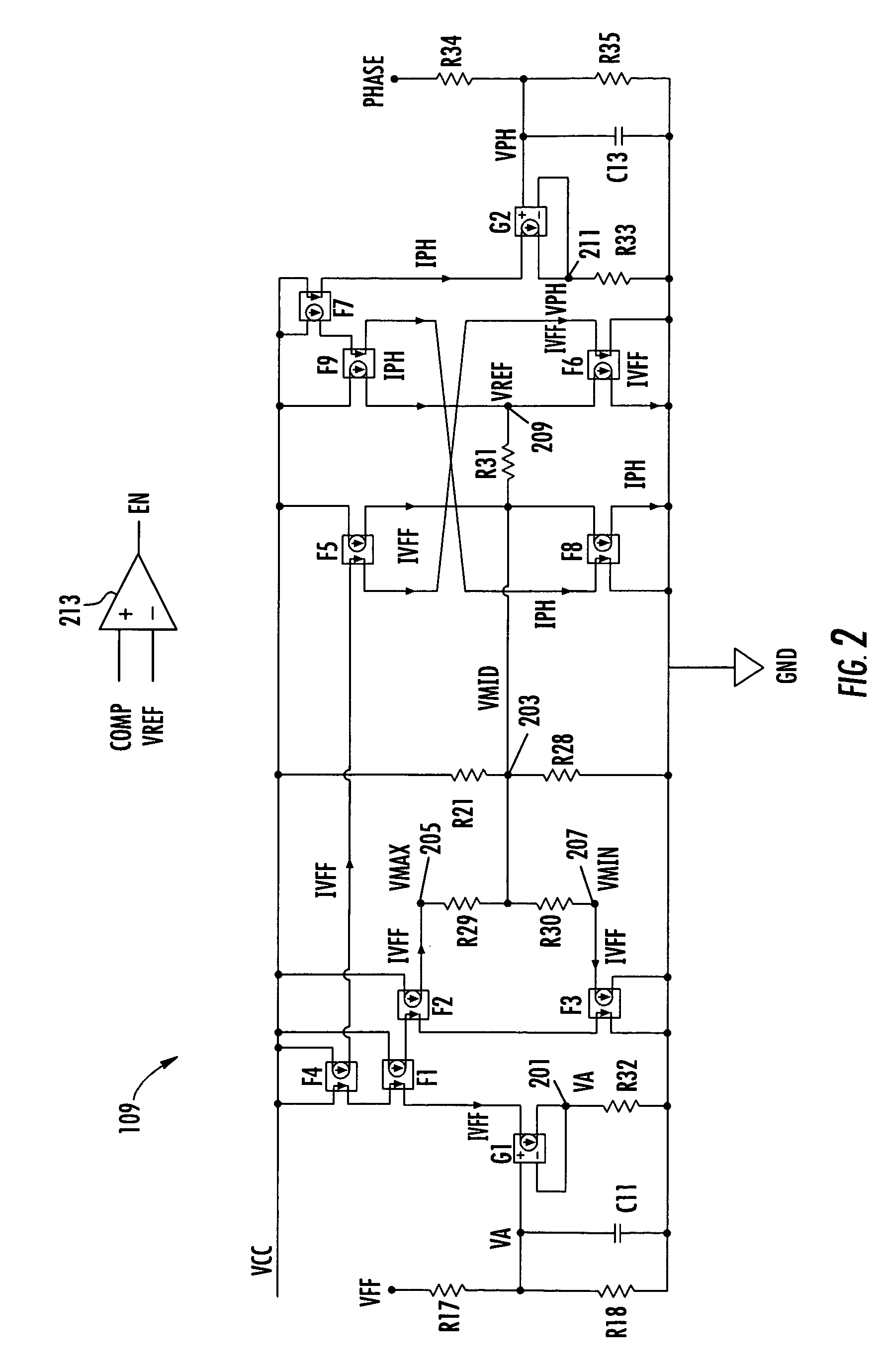
A method of starting a DC—DC converter into a precharged output voltage including generating a reference voltage having a linear relationship with the output voltage such that the reference voltage ranges between a minimum and maximum voltage level of a PWM triangular waveform as the output voltage ranges between zero and an input voltage level, and enabling output switching of the DC—DC converter when the reference voltage is approximately equal to a compensation signal generated by an error amplifier comparing the reference voltage with a feedback signal representative of the output voltage. Generating a reference voltage may include applying a first current based on the input voltage through two resistors to develop the minimum and maximum voltage levels, applying the first current in one direction through a third resistor, and applying a second current based on the output voltage through the third resistor in the opposite direction.

Description

CROSS-REFERENCE TO RELATED APPLICATIONS[0001]This application is based on U.S. Provisional Patent Application Ser. No. 60 / 550,292, filed on Mar. 5, 2004, which is herein incorporated by reference for all intents and purposes.[0002]This application is related to the following co-pending U.S. patent applications, which have a common assignee and at least one common inventor, and which are herein incorporated by reference in its entirety for all intents and purposes:[0003]Ser.DOCKETNo.NUMBERTITLE10 / 775,560INSL.0090STARTUP CIRCUITFOR A DC—DCCONVERTERBACKGROUND OF THE INVENTION[0004]1. Field of the Invention[0005]The present invention relates to PWM power regulators and / or DC—DC converters, and more particularly to a PWM switching DC—DC converter methodology for startup into a pre-charged or pre-biased load.[0006]2. Description of the Related Art[0007]The typical startup sequence of a pulse-width modulation (PWM) DC—DC converter is to ramp the non-inverting or positive “+” input of a fee...

Claims


Application Information

Patent Timeline
Patent Type & Authority Patents(United States)
IPC IPC(8): H03L7/00G05F1/40H02M3/07H02M3/10H02M3/155
CPCH02M1/36Y10S323/901H02M3/156
Inventor MEHAS, GUSTAVO J.LEITH, JAMES W.DAY, BRANDON D.
Owner INTERSIL INC
Learn More