
Liquid crystal display device

Inactive Publication Date: 2006-04-25
AU OPTRONICS CORP
View PDF11 Cites 240 Cited by
  • Summary
  • Abstract
  • Description
  • Claims
  • Application Information

AI Technical Summary

Benefits of technology

[0016]Various other objects, features, and attendant advantages of the present invention will become more fully appreciated as the same becomes better understood w

Problems solved by technology

This is an ideal solution but requires a special liquid crystal with a very fast response, so that the liquid crystals currently in use are not applicable due to their slow response.
For example, a present TN mode TFT-LCD has its on / off response time equivalent to about 1 refresh cycle (16.7 ms at 60 Hz refresh), however, the response time delays greatly in a halftone level, resulting in up to several to ten refreshes.
In particular, video images such as TV images mostly have halftone images, so that correct brightness can not be obtained.
Even when displaying text data on PCs, it takes a long time for a screen to become a good state where one can easily read if he performs a scroll operation.
As above, a deterioration in image quality when displaying moving pictures on a TFT-LCD results from that a transition of brightness of each pixel does not complete within one frame period of 16.7 ms.
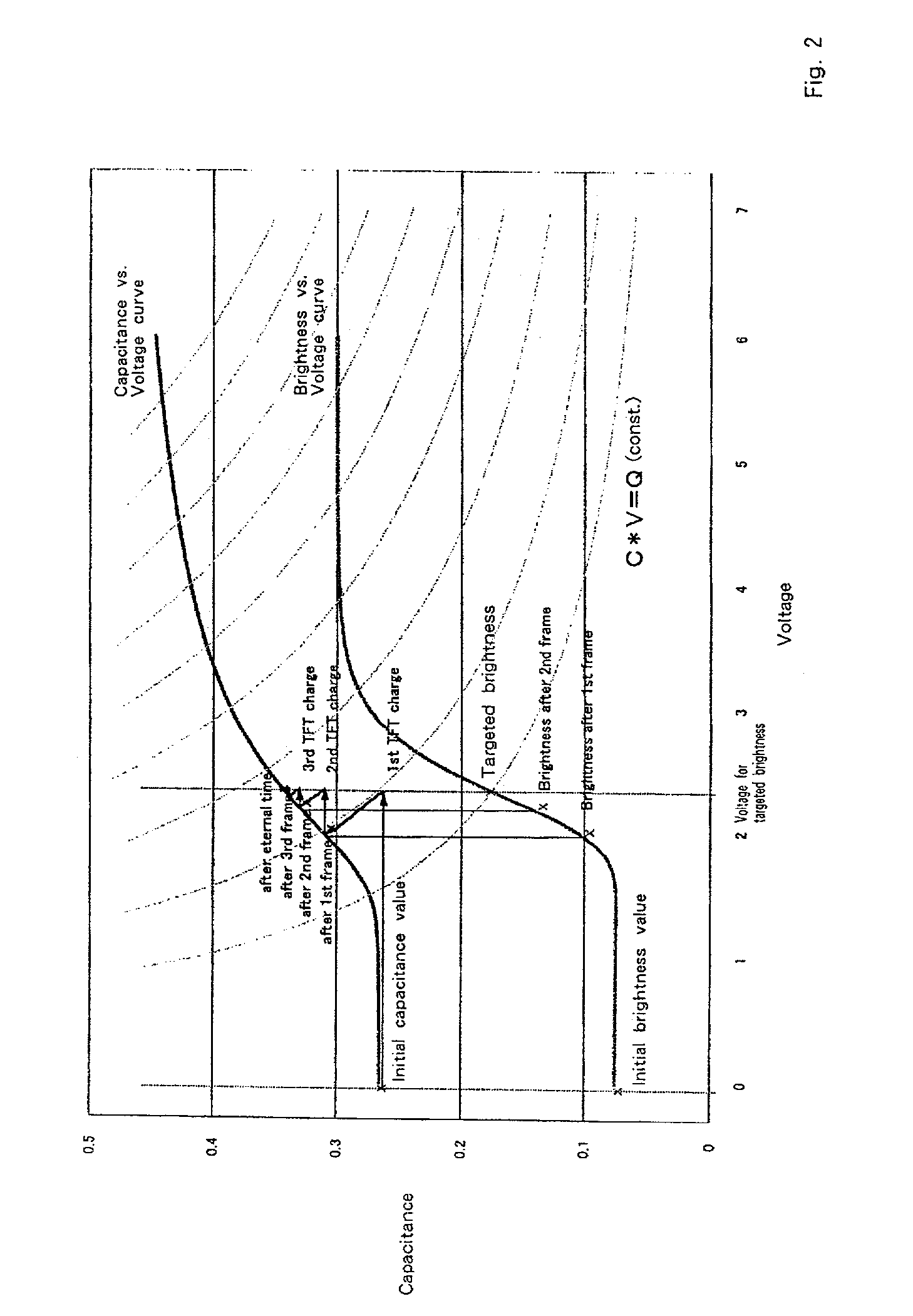
Namely, even in the case of liquid crystals with a fast response, the capacitance of the liquid crystal changes in principle of the liquid crystal driving, wherein the targeted brightness can not be reached only by one time of charge / discharge of TFT as long as using the normal driving method, as a matter of course, resulting in the display response being unable to catch up with the image when it changes for each frame.
The overdrive technique is relatively easily implemented only by changing the driving method and needs no change of a liquid crystal device itself, which is otherwise bothersome.
It is noted that liquid crystals are a viscous fluid and have a slow displacement speed per se, thus this would be regarded as the only cause of slow response time, however, a predicted voltage is 0V insofar as prediction so that it is impossible to represent the process of transition by means of voltage.
Furthermore, since the “cumulative response” and “viscosity” are nonlinear over the all gray levels, it is difficult indeed to get the necessary predicted values using the LPF.

Method used


Image

  • Liquid crystal display device
  • Liquid crystal display device
  • Liquid crystal display device

Examples


Embodiment Construction

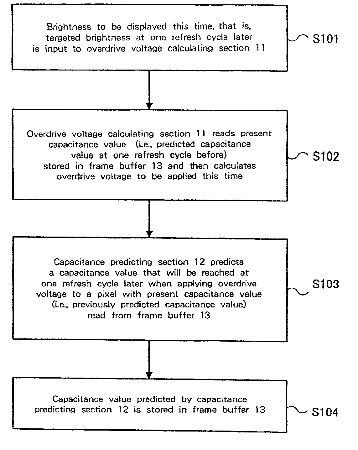
[0024]In order to achieve the above purposes, according to the present invention, when the gray level displayed changes for each pixel of a TFT-LCD, an excessive voltage (i.e., overdrive voltage) exceeding a targeted pixel value is applied with respect to a varied amount of the refresh cycle such that the brightness of a pixel reaches the targeted value within one refresh cycle time. In this regard, it is characterized in that a starting value for calculating the applied voltage is based on the capacitance of each pixel.

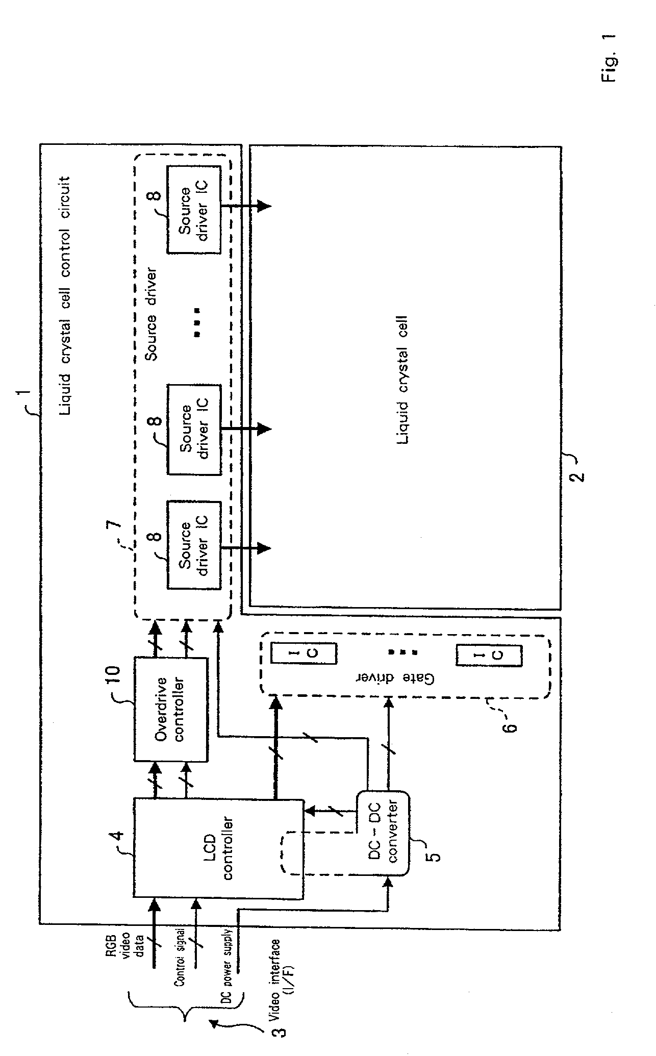
[0025]In another aspect of the present invention, there is provided a controller for a liquid crystal display device, comprising: voltage calculating means for calculating a voltage to be applied to a liquid crystal cell based on targeted brightness at one refresh cycle later corresponding to a pixel value to be displayed this time and a present capacitance value of the pixel that is predicted in advance; capacitance predicting means for predicting a capacitance valu...


PUM


Abstract

A liquid crystal display drive circuit includes capacitance predicting section for predicting a capacitance value each pixel will reach at one refresh cycle later when applying a predetermined voltage for targeted brightness, a frame buffer for storing the predicted capacitance value, and overdrive voltage calculating section for calculating a voltage to be applied to each pixel based on targeted brightness at one refresh cycle later and the stored capacitance value in frame buffer.

Description

BACKGROUND OF INVENTION[0001]1. Field to the Invention[0002]The present invention relates to a liquid crystal display device, and more particularly to a liquid crystal display device for improving the response time of the liquid crystal display.[0003]2. Background of the Invention[0004]Recently, a liquid crystal display (LCD) equipped with thin film transistors (TFT) has developed significantly due to its characteristics including light weight, thin shape and low power consumption. Conventionally, the use of LCDs for PCs was mainly directed to displaying static images, however, along with the progress of such LCDs, they have been substituted for CRTs such as when displaying moving pictures in a graphics system or displaying video images on monitors. Therefore, there is growing interest in displaying moving pictures using LCDs.[0005]While a CRT is in the impulse type of light emission, an LCD is in the hold type with emitting continuous light during a whole period of a frame, thereby...

Claims


Application Information

Patent Timeline
IPC IPC(8): G09G3/36G02F1/133G09G3/20
CPCG09G3/3611G09G2310/06G09G2340/16G09G2320/0285G09G2320/0252
Inventor SEKIYA, KAZUONAKAMURA, HAJIME
Owner AU OPTRONICS CORP
Learn More