X-ray diffraction apparatus

a diffraction apparatus and diffraction technology, applied in the direction of diffraction/refraction/reflection, material analysis using wave/particle radiation, instruments, etc., can solve the problems of high accuracy angular control, high cost of rotation control mechanism for rotation of x-ray detector, etc., and achieve high degree of resolution

Inactive Publication Date: 2006-04-25
RIGAKU CORP
View PDF5 Cites 38 Cited by
  • Summary
  • Abstract
  • Description
  • Claims
  • Application Information

AI Technical Summary

Benefits of technology

[0009]It is an object of the present invention to provide an X-ray diffraction apparatus making it possible to perform both th...

Problems solved by technology

On the other hand, in the in-plane diffraction measurement, the same X-ray detector must be rotated within a vertical plane, so that it is difficult to have the high-accuracy angular control because of the rotation against the gravitation.
Even ...

Method used


Image

  • X-ray diffraction apparatus
  • X-ray diffraction apparatus
  • X-ray diffraction apparatus

Examples


Embodiment Construction

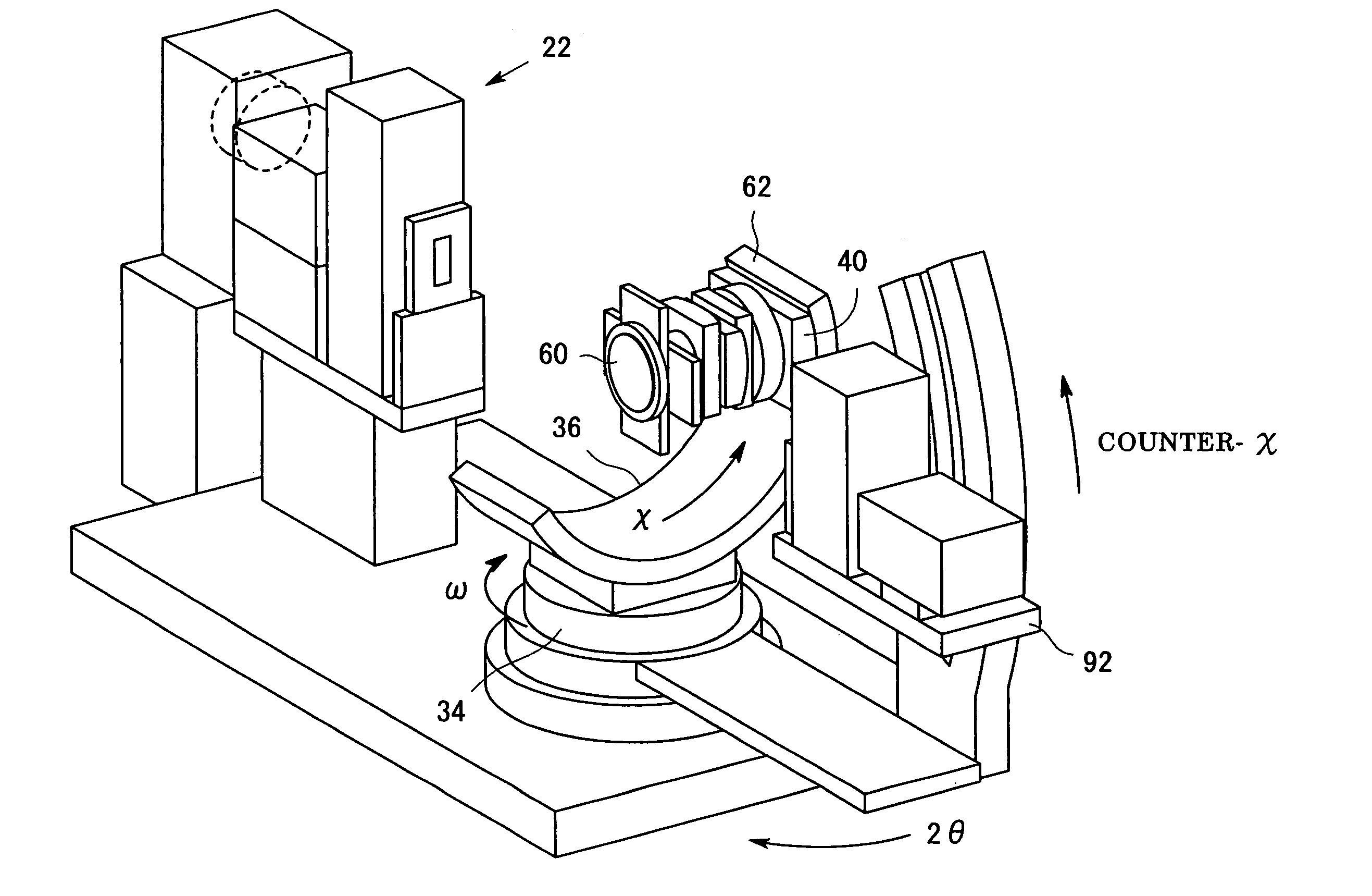
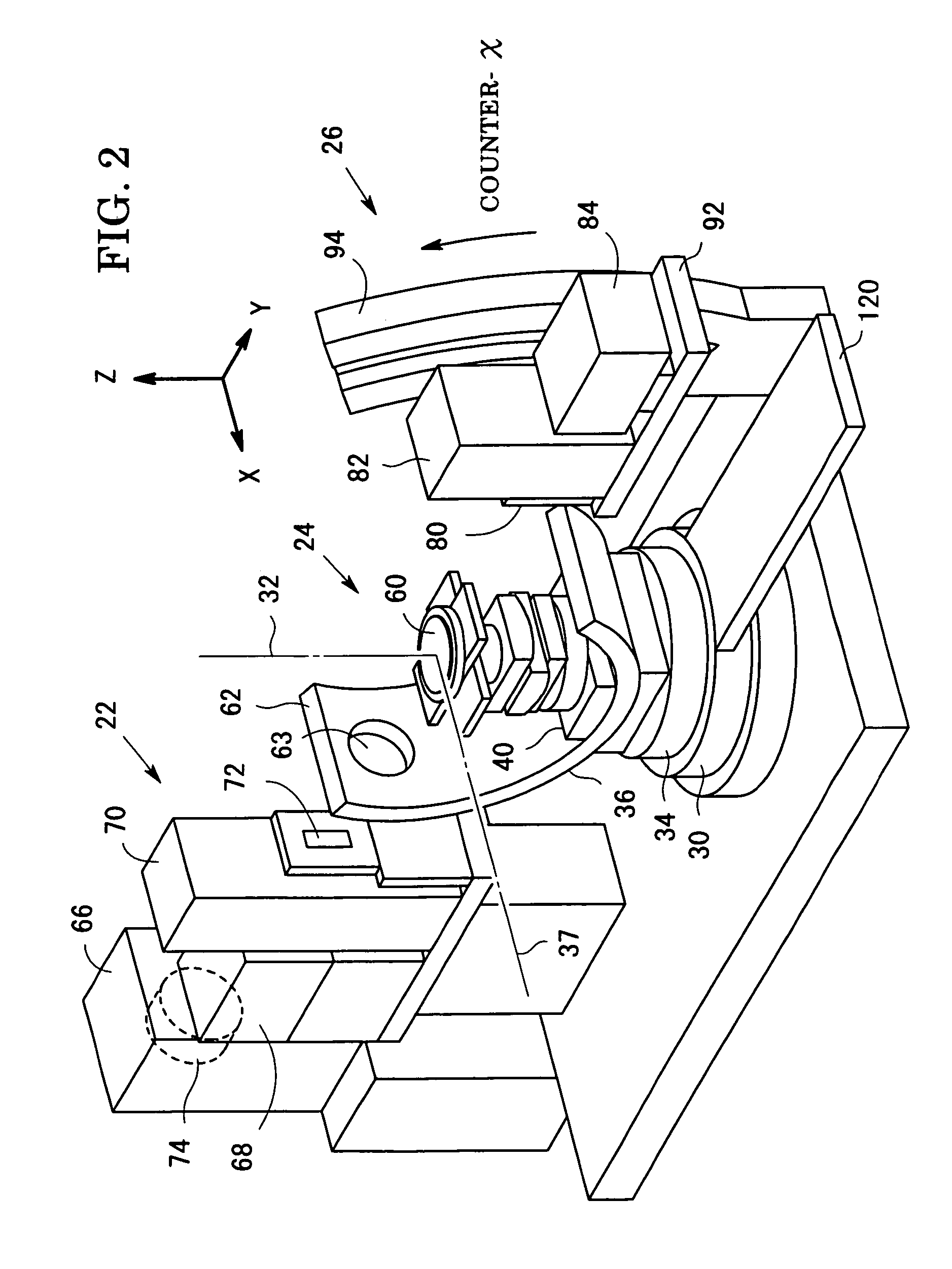
[0041]An embodiment according to the present invention will be described below with reference to the drawings. FIG. 2 is a perspective view of an X-ray diffraction apparatus according to the embodiment. The X-ray diffraction apparatus includes an incident optical system 22, a sample support mechanism 24, a receiving optical system 26, and an receiving-optical-system turntable 30.

[0042]First, the sample support mechanism 24 and the receiving-optical-system turntable 30 will be described. FIG. 3 is a perspective view of the sample support mechanism 24 and the receiving-optical-system turntable 30 and FIG. 4 is a perspective view showing their movements only. Referring to FIGS. 3 and 4, an X-axis and a Y-axis are defined in a horizontal plane, and a Z-axis is defined to be perpendicular to the horizontal plane, resulting in a three-dimensional rectangular coordinate system. A stationary base 28 is provided with the receiving-optical-system turntable 30 which can turn around an axis of ...


PUM


Abstract

An -ray emitted from an incident optical system is incident on a sample supported by a sample support mechanism, and a diffracted X-ray is detected by a receiving optical system. The incident optical system includes an X-ray source and a multilayer-film mirror. An attitude controlling unit of the sample support mechanism switches a condition of the sample support mechanism from a state maintaining the sample to have a first attitude in which a normal line of the surface of the sample is parallel with a first axis of rotation to another state maintaining the sample to have a second attitude in which the normal line of the surface of the sample is perpendicular to the first axis of rotation. When the receiving optical system is rotated around the first axis of rotation while maintaining the sample in the first attitude, in-plane diffraction measurement is possible. On the other hand, when the receiving optical system is rotated in the same way while maintaining the sample in the second attitude, out-of-plane diffraction measurement is possible.

Description

BACKGROUND OF THE INVENTION[0001]1. Field of the Invention[0002]The present invention relates to an X-ray diffraction apparatus making it possible to execute in-plane diffraction measurement.[0003]2. Description of the Related Art[0004]The in-plane diffraction measurement, as shown in FIG. 1A, designates a measuring technique in that an X-ray 12 is incident on a sample surface 10 at a grazing incident angle α (a very small incident angle of about 0.1° to 0.5°, for example) and a diffracted X-ray 14 is detected at an outgoing angle β grazing from the sample surface 10. A circle 16 indicated by an imaginary line denotes a plane including the sample surface 10. The in-plane diffraction is a phenomenon in which an X-ray is diffracted on a crystal lattice surface substantially perpendicular to the sample surface. Since the diffracted X-ray is detected within a plane substantially flush with the plane 16 including the sample surface 10, this technique is called as in-plane. When the in-pl...

Claims


Application Information

Patent Timeline
IPC IPC(8): G01N23/20G01N23/207G21K1/06
CPCG21K1/06G01N23/20A01K5/01
Inventor OMOTE, KAZUHIKO
Owner RIGAKU CORP
Why Eureka
Try Eureka