Trimmer attachment

a technology of attachment and trimmer head, which is applied in the field of fully adjustable lightweight trimmer attachment assembly, can solve the problems of difficult to hold the trimmer head at a constant height, incurring back, shoulder, arm pain, etc., and achieves the effects of minimizing storage space, convenient and comfortable use, and minimizing storage spa

Inactive Publication Date: 2006-05-02
POPP LAWRENCE
View PDF48 Cites 20 Cited by
  • Summary
  • Abstract
  • Description
  • Claims
  • Application Information

AI Technical Summary

Benefits of technology

[0007]The present invention overcomes the above-identified problems and provides a distinct advance in the art of string trimmers. More particularly, the present invention provides a fully-adjustable lightweight attachment assembly for a trimmer that provides lateral stability for the trimmer and supports the trimmer's weight at a uniform height, while allowing the trimmer to move in any direction. The attachment assembly broadly comprises a wheel to support the weight of the trimmer, a rod extending from the wheel, and a mounting mechanism for mounting the rod to the trimmer.

Problems solved by technology

However, most trimmers are heavy and unwieldy, thereby making their use difficult.
For example, users must support the trimmer's full weight at a constant height above a lawn, thereby incurring back, shoulder, and arm pain.
Additionally, it is often very difficult to hold a trimmer head at a constant height.
However, many attachments are themselves heavy and unwieldy, thereby making their installation, use, and storage difficult.
Relatively small and lightweight attachments have also been developed, but they do not provide sufficient adjustability, and the limited adjustment cannot be accomplished without the use of tools, thereby complicating their use.

Method used


Image

  • Trimmer attachment
  • Trimmer attachment
  • Trimmer attachment

Examples


Embodiment Construction

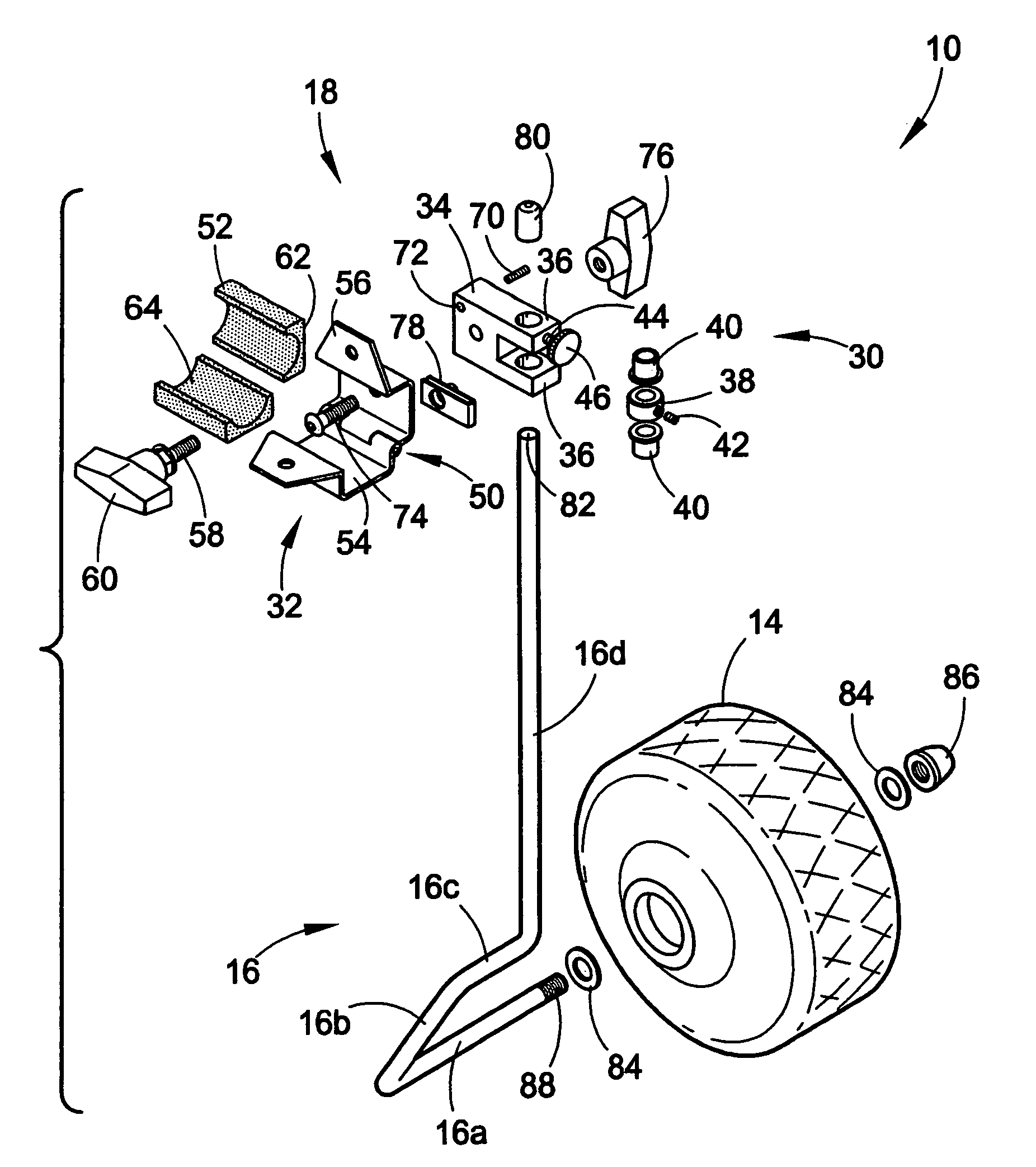
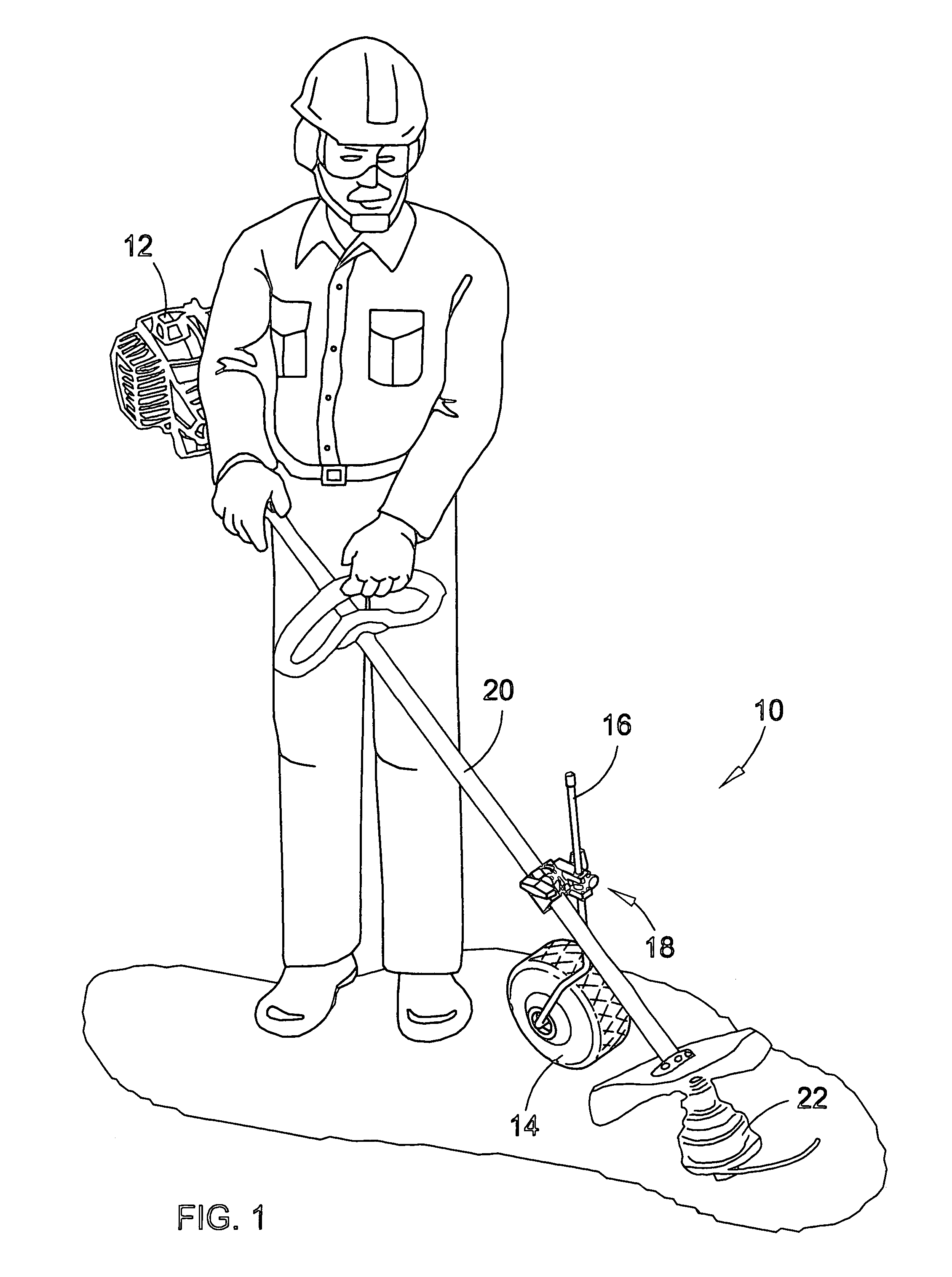
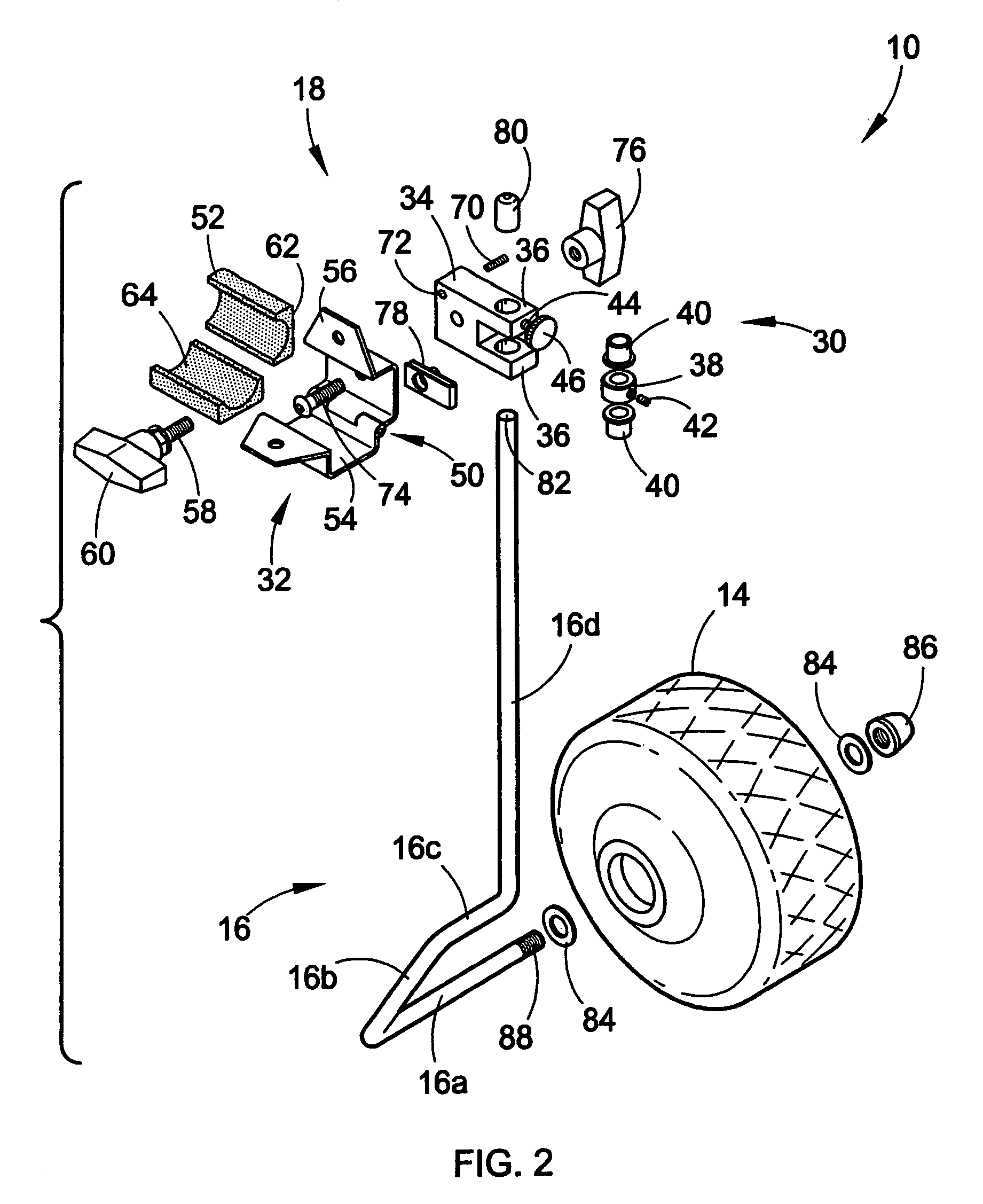
[0022]Referring to FIG. 1, the preferred attachment assembly 10 constructed in accordance with a preferred embodiment of the present invention is illustrated supporting a gas powered string trimmer 12. The attachment assembly 10 broadly comprises a wheel 14 to support the weight of the trimmer 12, a rod 16 extending from the wheel 14, and a mounting mechanism 18 for rotationally mounting the rod 16 to a shaft 20 of the trimmer 12.

[0023]The wheel 14 may be formed of any suitable material but is preferably formed of hollow plastic. The wheel 14 is preferably approximately three and one half inches wide and approximately seven inches in diameter. The wheel 14 preferably presents a substantially straight ground contact line extending substantially the entire width of the wheel 14, thereby preventing the wheel 14 from rolling over laterally. In other words, the wheel 14 is preferably laterally flat, rather than laterally rounded. Thus, the wheel 14 is operable to easily roll over rough g...


PUM


Abstract

A fully-adjustable lightweight trimmer attachment assembly (10) broadly comprises a wheel (14), a rod (16) extending from the wheel (14), and a mounting mechanism (18) for rotationally mounting the rod (16) to a trimmer (12). The rod (16) preferably includes an axle section (16a) through the wheel (14), a trailing section (16b) perpendicular to the axle section (16a), a centering section (16c) parallel to the axle section (16a), and a vertical section (16d) aligned at ninety degrees to the centering section (16c) and at sixty degrees to the trailing section (16b). With the vertical section (16d) vertical, the trailing section (16b) forces the wheel (14) to follow the vertical section (16d), providing a castering effect. The mounting mechanism (18) includes a rod mount (30) rotationally secured to the vertical section (16d) and a shaft mount (32) operable to be secured to the trimmer (12) and rotate about the rod mount (30).

Description

BACKGROUND OF THE INVENTION[0001]1. Field of the Invention[0002]The present invention relates to landscaping implements. More particularly, the present invention relates to a fully-adjustable lightweight trimmer attachment assembly that provides lateral stability for the trimmer and supports the trimmer's weight at a uniform height, while allowing the trimmer to move in any direction.[0003]2. Description of Prior Art[0004]String trimmers are commonly used to cut or trim grass, weeds, and other plants. However, most trimmers are heavy and unwieldy, thereby making their use difficult. For example, users must support the trimmer's full weight at a constant height above a lawn, thereby incurring back, shoulder, and arm pain. Additionally, it is often very difficult to hold a trimmer head at a constant height.[0005]In response, trimmer attachments have been designed to support trimmers at a constant height to alleviate some of these problems. However, many attachments are themselves heav...

Claims


Application Information

Patent Timeline
Patent Type & Authority Patents(United States)
IPC IPC(8): A01D34/84A01D15/00A01D34/416
CPCA01D34/001A01D34/90A01D34/84A01D34/416
Inventor POPP, LAWRENCE
Owner POPP LAWRENCE
Why Eureka
Try Eureka