Z-axis angular rate sensor

a technology of angular rate sensor and z-axis, which is applied in the direction of acceleration measurement using interia force, turn-sensitive devices, instruments, etc., can solve the problems of increasing system complexity or fabrication processing, unable to scale up to high-volume, and low-cost manufacturing

Active Publication Date: 2006-05-02
ROHM CO LTD
View PDF16 Cites 91 Cited by
  • Summary
  • Abstract
  • Description
  • Claims
  • Application Information

AI Technical Summary

Benefits of technology

[0014]The invention is a planar oscillatory rate sensor with unique structural linkage configurations that result in fundamental “tuning fork” anti-phase type motion with negligible phase error. The presence of fundamental anti-phase motion relaxes burdens on system control of frequencies and phases, fabrication tolerances, and mechanical tuning of individual sensors. When the two linked masses are vibrated along an in-plane x-axis, and the substrate is rotated about an out-of-plane z-axis, the masses react due to the Coriolis force and oscillate in plane along the y-axis. The y-reaction is likewise anti-phase and differential sensing and demodulation results in extraction of a rate-of-rotation signal from the y-motion, wherein acceleration signals are eliminated as common-mode.

Problems solved by technology

Traditional military-grade gyroscope fabrication techniques are not scalable to high-volume, low-cost manufacturing.
It can be accomplished by various techniques, most of which increase system complexity or fabrication processing.
MEMS rate sensors in the prior art have numerous technical challenges related to complex system control, minute sense signals, thermal variation, and ever-present error signals.

Method used


Image

  • Z-axis angular rate sensor
  • Z-axis angular rate sensor
  • Z-axis angular rate sensor

Examples


Embodiment Construction

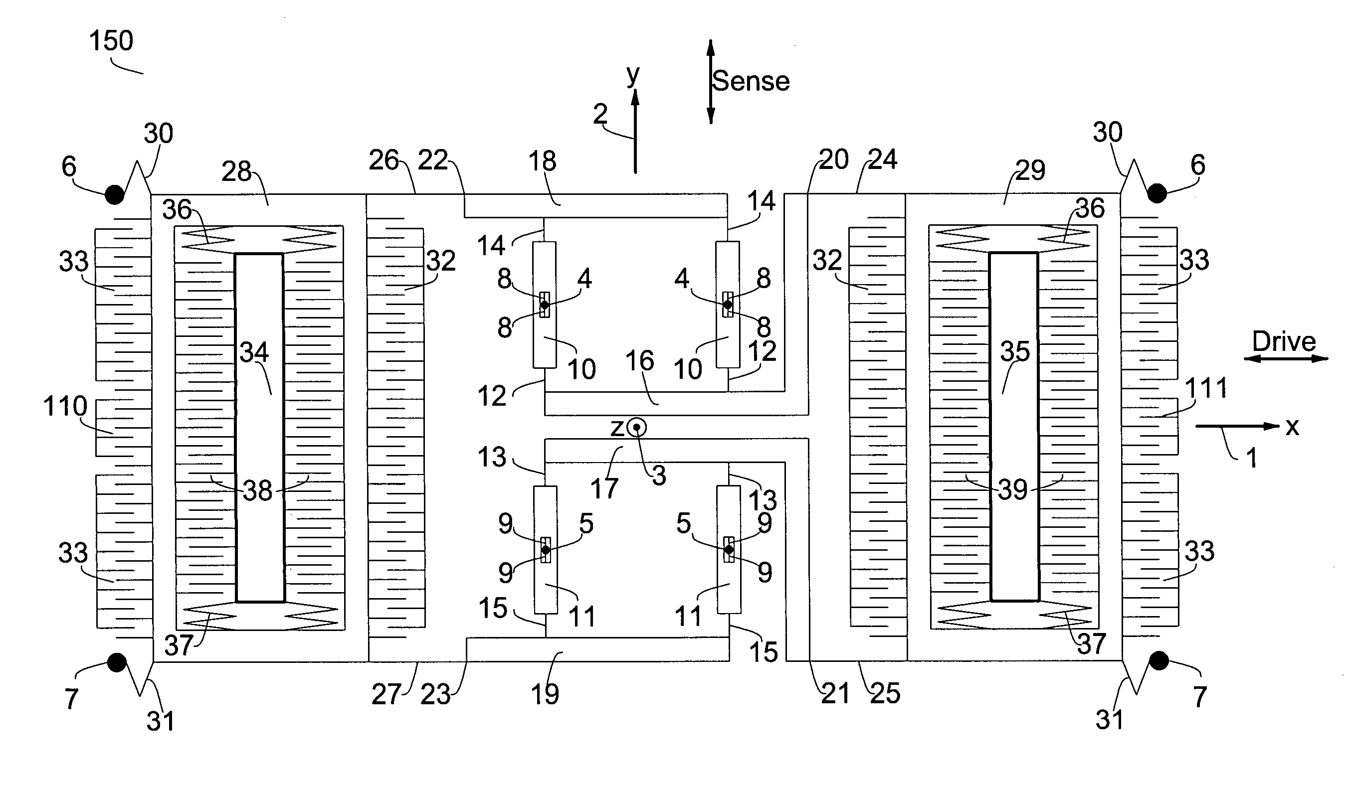
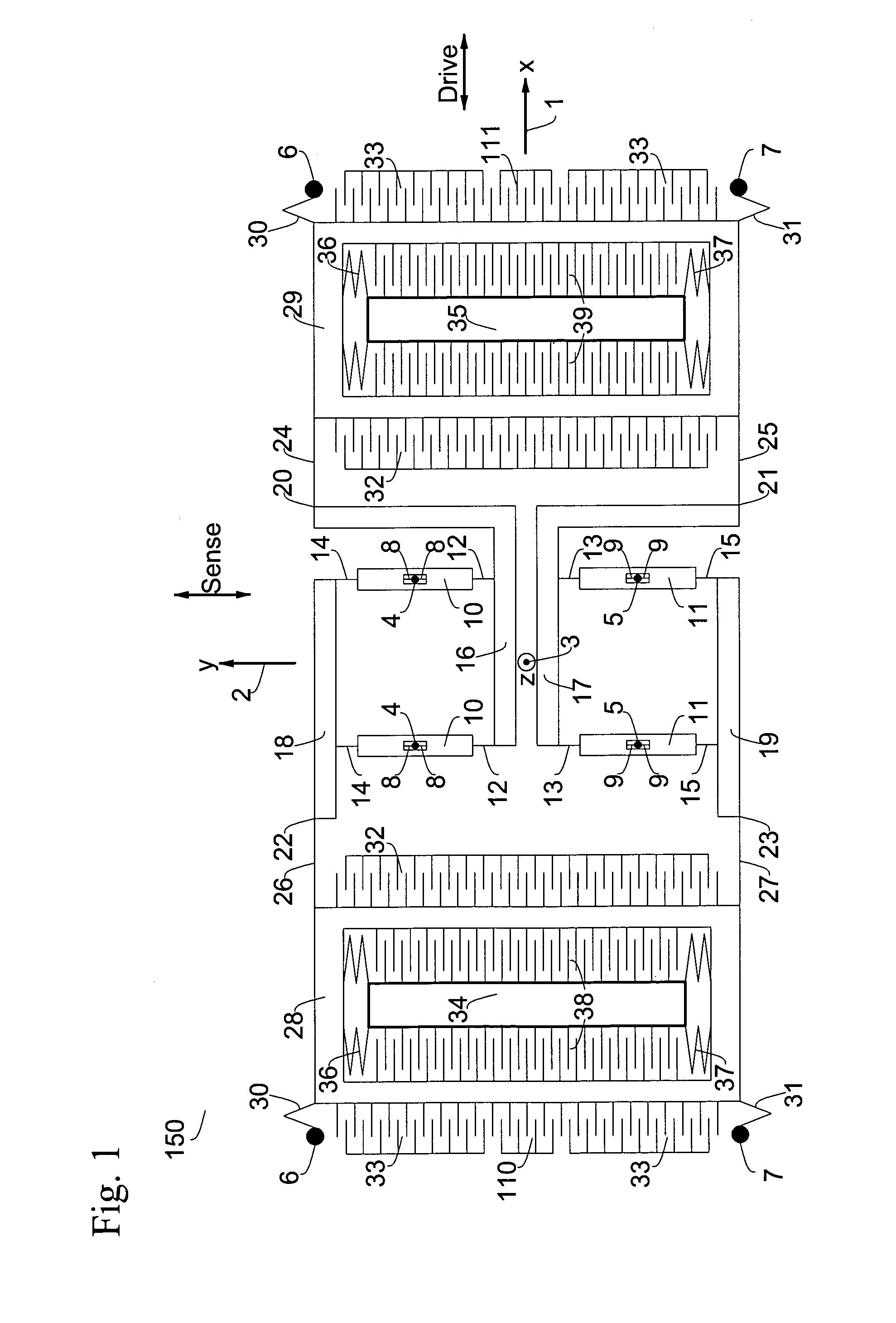
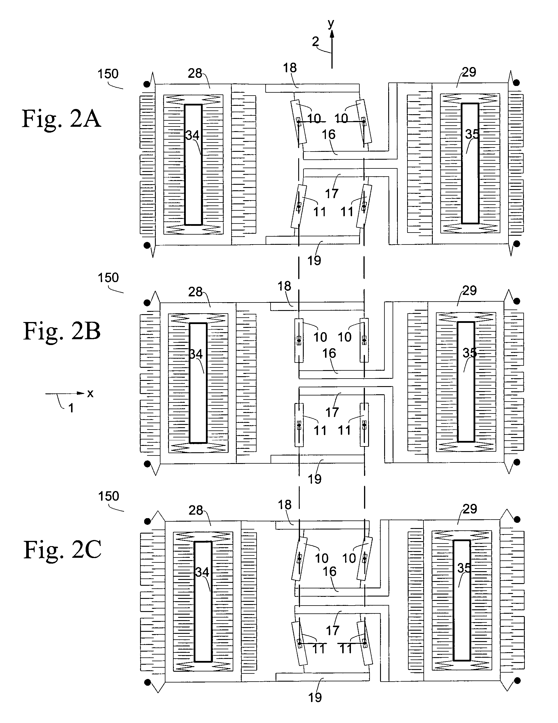
[0035]The rate sensor of the present invention satisfies critical gyrodynamic aspects by virtue of the sensor's mechanical linkages which give rise to fundamental anti-phase motion of its two oscillating masses. This is in contrast to the dynamics of prior art coupled oscillators, which have “symmetric” and “antisymmetric” resonant modes with the undesired symmetric mode being fundamental.

[0036]In the present invention, anti-phase operation is accomplished by unique structural linkage configurations resulting in negligible phase error. The linkage dictates mechanical dynamics, which can have anti-phase motion as the fundamental mode, with insensitivity to small mass or spring imbalances. The structural symmetries produce linear motions in a robust fashion. Other oscillation modes can be of higher order with comfortable mode separation. The mechanical design is preferably realized using any of a variety of MEMS fabrication technologies, including, but not limited to, Deep Reactive Io...


PUM


Abstract

An oscillatory rate sensor is described for sensing rotation about the “z-axis”. It is tuning-fork in nature with structural linkages and dynamics such that fundamental anti-phase oscillation of two proof masses is accomplished by virtue of the mechanical linkages.

Description

REFERENCE TO RELATED APPLICATIONS[0001]This application claims an invention which was disclosed in Provisional Application No. 60 / 505,990, filed Sep. 25, 2003, entitled “Z-AXIS ANGULAR RATE SENSOR WITH UNIQUE DYNAMICS”. The benefit under 35 USC §119(e) of the United States provisional application is hereby claimed, and the aforementioned application is hereby incorporated herein by reference.BACKGROUND OF THE INVENTION[0002]1. Field of the Invention[0003]The invention pertains to the field of microdevices and microstructures. More particularly, the invention pertains to angular rate sensors.[0004]2. Description of Related Art[0005]There is considerable interest in the development of low-cost, reliable, high-quality gyroscopic rate-of-rotation sensors enabled by developments in Micro Electro-Mechanical Systems (MEMS) technology. Traditional military-grade gyroscope fabrication techniques are not scalable to high-volume, low-cost manufacturing. MEMS technology utilizes semiconductor f...

Claims


Application Information

Patent Timeline
Patent Type & Authority Patents(United States)
IPC IPC(8): G01P9/04G01C19/56
CPCG01C19/5747G01C19/5719G01P15/08
Inventor CHOJNACKI, ERIC P.SHEN-EPSTEIN, JUNE P.NENADIC, NENADSTIRLING, NATHAN L.NISTOR, VASILE
Owner ROHM CO LTD
Why Eureka
Try Eureka