
Ammunition projectile having enhanced aerodynamic profile

a projectile and aerodynamic technology, applied in the field of ammunition, can solve the problems of toxic lead and relatively inefficient aerodynamic effect, and achieve the effects of enhancing the aerodynamic properties of the projectile, reducing the resistance to movement through air, and enhancing the accuracy of delivery to a targ

Inactive Publication Date: 2006-05-02
LONE STAR FUTURE WEAPONS LLC +2
View PDF7 Cites 13 Cited by
  • Summary
  • Abstract
  • Description
  • Claims
  • Application Information

AI Technical Summary

Benefits of technology

The solution results in a 50% or greater reduction in aerodynamic drag, enabling higher velocity and accuracy at extended ranges, with enhanced disintegration into small fragments, minimizing collateral damage and improving terminal ballistics.

Problems solved by technology

Lead, however, has been found to be toxic and its elimination from gun ammunition projectiles is currently in progress.
There are myriad problems associated with the manufacture of projectiles employing metal powder(s) as the basic material of the projectile.
One of these problems relates to the ultimate formation of a pressed powder compact into an aerodynamically acceptable projectile.
However, hollow pointed projectiles suffer from several shortcomings, such as their tendency to misfeed from magazines into the breech of a semi-automatic or automatic weapon; their relatively inefficient aerodynamic effect upon the flight of the projectile to a target; and other ill effects, all of which must be balanced against the requirement that the projectile disintegrate to the fullest extent upon striking a target.

Method used


Image

  • Ammunition projectile having enhanced aerodynamic profile
  • Ammunition projectile having enhanced aerodynamic profile
  • Ammunition projectile having enhanced aerodynamic profile

Examples


Embodiment Construction

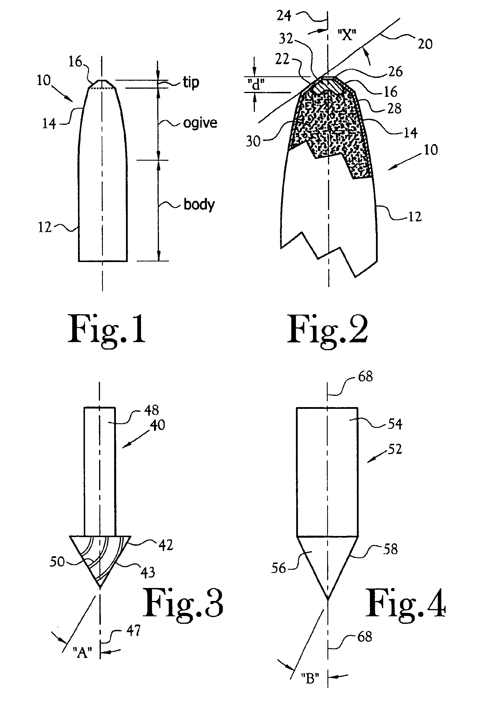
[0028]Referring to FIG. 1, there is depicted, somewhat exaggerated for purposes of illustration, a projectile 10 including a body portion 12 of generally straight cylindrical geometry, an ogive portion 14, and a tipped portion 16 at the extreme distal end 16 of the ogive. The tipped ogive portion of the projectile defines the leading end of the projectile when it is fired from a weapon. As noted the angularity of the tipped portion 16 is somewhat exaggerated for illustration purposes.

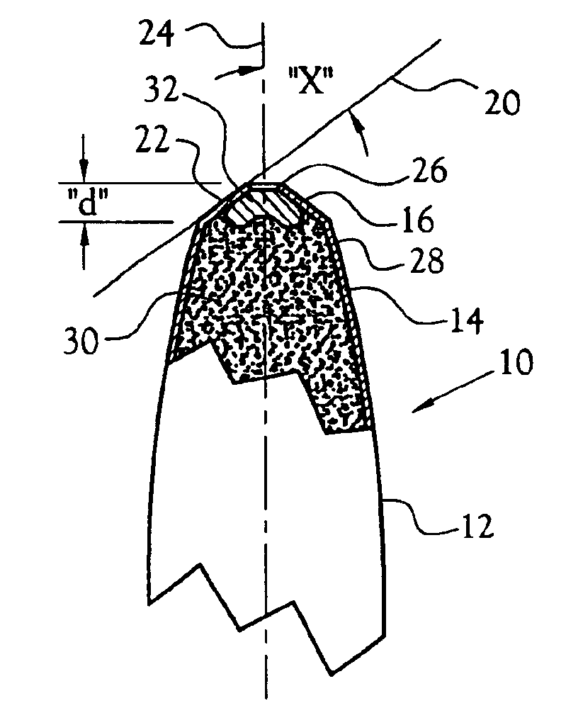
[0029]FIG. 2 depicts an enlarged and even more exaggerated embodiment of the leading end of the projectile depicted in FIG. 1. In FIG. 2, it may be seen that the extended side surface line 20 of the side 22 of the tip defines an angle “X31 relative to the longitudinal centerline 24 of the projectile. The depth “d” of the tip is measured from distal end 26 of the jacket 28 of the projectile inwardly along the longitudinal centerline of the projectile.

[0030]The projectile of FIG. 2 comprises a metal, pre...


PUM


Abstract

A projectile 10 for gun ammunition of a size not greater than 50 caliber comprising a solid metal jacket 82 of generally cup-shaped geometry and having a closed end 102 and an open end 88, a core 84 formed from a mixture of metal powders, not including lead, which mixture is cold-pressed into a self-supporting compact and disposed within said jacket, the core incompletely filling the jacket, an ogive 14 having an outer surface and defined on the initially open end of said jacket, and a conical tip 122 defined on the distal end 118 of said ogive, the tip having an outer surface 22 which defines an angle with respect to the longitudinal centerline 24 of the projectile that is greater than the angle defined by the ogive with respect to the longitudinal centerline of the projectile. A method is disclosed.

Description

RELATED APPLICATIONS[0001]This application is a non-provisional application and claims priority based on Provisional Application Ser. No. 60 / 366,132 filed Mar. 20, 2002 entitled AMMUNITION PROJECTILE HAVING ENHANCED AERODYNAMIC PROFILE.FIELD OF INVENTION[0002]The present invention relates to gun ammunition and particularly to projectiles for gun ammunition.BACKGROUND OF INVENTION[0003]For many years, lead has been the standard metal for use in the manufacture of projectiles for gun ammunition. Lead, however, has been found to be toxic and its elimination from gun ammunition projectiles is currently in progress. Because of this long-standing reliance upon lead as the basic metal for the manufacture of gun ammunition projectiles, the art / science of manufacture of gun ammunition projectiles has languished in mediocrity.[0004]Of recent vintage are gun ammunition projectiles formed from metal powders which are compacted into shaped projectiles or which are compacted and thereafter formed...

Claims


Application Information

Patent Timeline
Patent Type & Authority Patents(United States)
IPC IPC(8): F42B10/00F42B10/46F42B12/34F42B12/74
CPCF42B10/46F42B12/74F42B12/34
Inventor BEAL, HAROLD F.
Owner LONE STAR FUTURE WEAPONS LLC
Learn More