Eureka AIR delivers breakthrough ideas for toughest innovation challenges, trusted by R&D personnel around the world.

Security barrier

Inactive Publication Date: 2006-05-02
INTERTEX BARRIERS & BOOTHS
View PDF18 Cites 22 Cited by
  • Summary
  • Abstract
  • Description
  • Claims
  • Application Information

AI Technical Summary

Benefits of technology

[0013]Accordingly, it is an object of the invention to provide a security barrier apparatus and system that can be deployed rapidly in an emergency.
[0018]Still another object of the invention is to provide a security barrier apparatus and system that provides real time status of the device and system components.
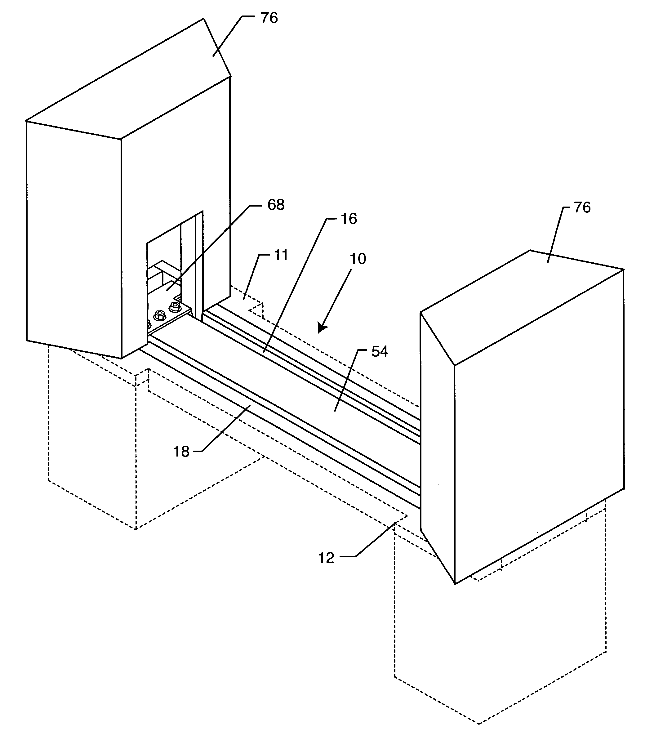
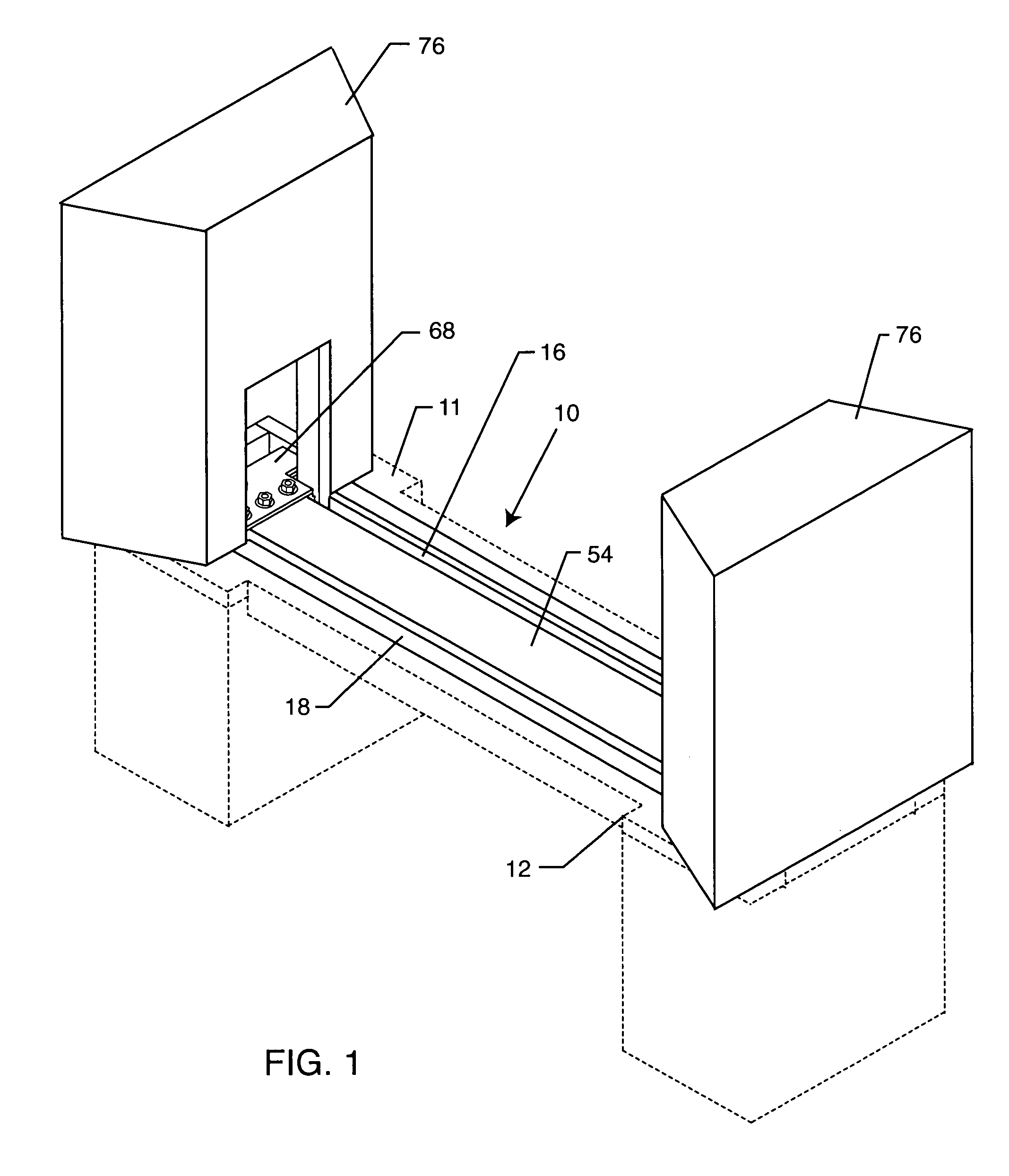
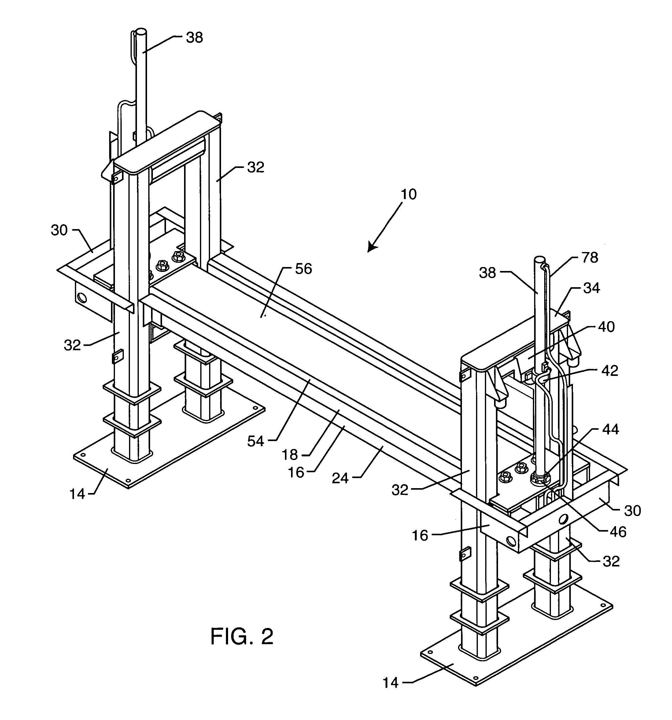
[0027]When the beam is in its fully-lowered position, the top of the beam is flush with the existing grade and vehicles may travel freely over it and across the barrier. In its fully raised position, the beam presents an obstacle thirty-six inches above grade. The vertical posts at each end constrain the beam in the event of a vehicle collision with the barrier. Impact force is transmitted through the beam to the posts. Each post is anchored by a subterranean concrete and rebar reinforced structure sufficient to restrain the vehicle from forward movement.

Problems solved by technology

Such foundations are visually intrusive, may take up a great deal of space, and often make it difficult for authorized vehicles to gain access to the facilities.
Guard gates having moving fences controlled by personnel can be effective for controlling the flow of pedestrian access to facilities, but they generally are not very effective for stopping vehicles, especially large ones, which can break right through them.
Another problem inherent in known roadway security barriers, especially those having enough mass to stop a large vehicle, is that they are slow to react and are not effective in stopping pedestrians.

Method used


Image

  • Security barrier
  • Security barrier
  • Security barrier

Examples


Embodiment Construction

[0047]In the following description of the present invention, reference is made to the accompanying drawings, which form a part thereof, and in which are shown, by way of illustration, exemplary embodiments illustrating the principles of the present invention and how it may be practiced. It is to be understood that other embodiments may be utilized to practice the present invention and structural and functional changes may be made thereto without departing from the scope of the present invention.

[0048]A security barrier of the present invention is illustrated in FIGS. 1 through 7 and indicated generally by the numeral 10. Barrier 10 is mounted in an excavation 11 that is partly below grade 12. In the preferred embodiment of the invention, a pair of vertical posts 32 is mounted on a mounting plate 14 located below grade 12 at each end of barrier 10. Posts 32 extend above grade and are connected by top plate 34.

[0049]Pan 16 is attached to posts 32 such that lip 18 of pan 16 is generall...


PUM


Abstract

A security barrier includes a horizontal composite beam extending across a roadway is mounted between vertical posts at either end of the beam. Hydraulic cylinders fastened at each beam end and to the vertical posts cause the beam to be raised and lowered, as needed. When the beam is at its lowest position, it allows for the normal flow of traffic over the top of the beam. When the beam is in its fully-raised position, it provides a vehicle barrier thirty-six inches above grade. A hydraulic power unit and components control the direction and speed of beam movement.The security barrier also includes electronic control and monitoring of the beam, and hydraulic system.

Description

RELATED APPLICATIONS[0001]This application claims the benefit of U.S. Provisional Patent Application No. 60 / 467,087, filed May 1, 2003, incorporated herein by reference.BACKGROUND OF THE INVENTION[0002]1. Field of the Invention[0003]The present invention relates to security devices, and more particularly to an apparatus and system that can rapidly block access to vehicular and pedestrian traffic during an emergency, but which can also allow for the orderly flow and control of traffic during non-emergency situations.[0004]2. General Background and State of the Art[0005]The need to control access to secure facilities by vehicular traffic and pedestrians, particularly to national consulates and embassies, has never been more important. Since the Sep. 11, 2001, World Trade Center attacks, the threat to government and secure facilities and the need to protect them, has become a high priority.[0006]Several forms of roadway security barriers have been used to control access by vehicles to ...

Claims


Application Information

Patent Timeline
IPC IPC(8): E01F13/00E01F13/12
CPCE01F13/048E01F13/044
Inventor DONOHOE, DALE R.ANDERSON, JEFFREY G.LOPEZ, JOE L.COOK, GREG L.BEST, KENNETH J.SHRECKENGOST, RODNEY P.LYON, ROBERT L.GARRETT, JOHN T.
Owner INTERTEX BARRIERS & BOOTHS
Why Eureka
Eureka Blog
Learn More