Tool holder

a tool and tool head technology, applied in the field of tool head holders, can solve the problems of large force and difficulty in reducing the tip run-out of the tool, and achieve the effects of small force, high run-out accuracy, and easy correction of the tip run-out of the cutting tool

Inactive Publication Date: 2006-05-02
NIKKEN KOSAKUSHO WORKS LTD
View PDF42 Cites 20 Cited by
  • Summary
  • Abstract
  • Description
  • Claims
  • Application Information

AI Technical Summary

Benefits of technology

[0017]In view of the foregoing, an object of the present invention is to provide a tool holder equipped with a tip run-out correction function which enables an operator to easily correct tip run-out of a cutting tool with small force, can maintain high run-out accuracy attained through correction, and can be applied to holders used for cutting tools of large diameter.
[0022]Preferably, the ring member includes a balance member for preventing unbalanced rotation of the ring member, which would otherwise result from provision of the eccentric cam.
[0028]Preferably, the ring member includes a balance member for preventing unbalanced rotation of the ring member, which would otherwise result from provision of the ball element.

Problems solved by technology

In other words, even when a precision chuck is used for a tool holder of a burnishing reamer, drill, or the like, difficulty is encountered in reducing run-out of the tip of the tool to zero.
Therefore, correction of tip run-out requires a large force.

Method used


Image

  • Tool holder
  • Tool holder
  • Tool holder

Examples


first embodiment

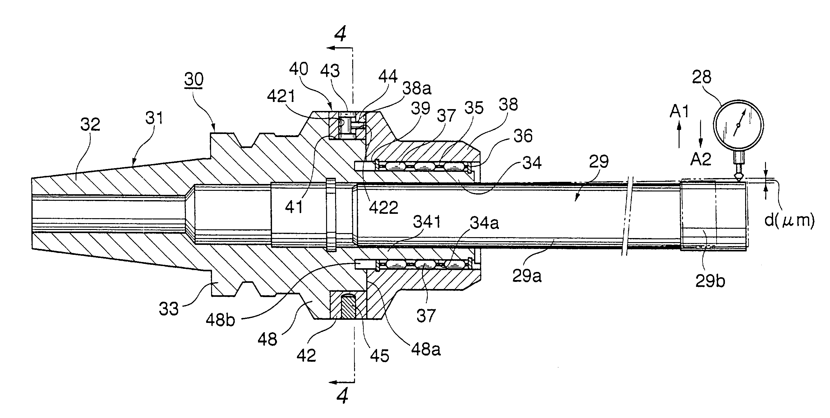
[0072]In the above-described first embodiment, the base end portion 341 of the chuck sleeve 34, which is continuous with the cylindrical support portion 48, is elastically deformed in a radial direction in order to reduce the tip run-out of the cutting tool 29 to zero, through an operation of rotating the eccentric cam 43 provided in the ring member 42, which is fitted onto the cylindrical support portion 48 of the holder body 31, to thereby adjust the pressing force which the pin 44 applies to the rear end face 38a of the clamp sleeve 38. Therefore, the tip run-out of the cutting tool 29 can be corrected with small force, and high run-out accuracy can be maintained stably. In addition, the run-out correction mechanism can easily be applied to tool holders for cutting tools of large diameter.

second embodiment

[0073]Next, the present invention will be described with reference to FIGS. 6 and 7.

[0074]FIG. 6 is a longitudinal cross section of a tool holder equipped with a tip run-out correcting mechanism according to the second embodiment of the present invention; and FIG. 7 is an enlarged cross section of the tool holder of the second embodiment, taken along line 7—7 in FIG. 6.

[0075]As shown in FIG. 6, a tool holder 50 for holding a cutting tool 29 such as a drill or a burnishing reamer has a holder body 51. The holder body 51 includes a taper shank portion 52 to be attached to a main spindle of an unillustrated machine tool; a flange portion 53, which is formed at an end of the shank portion 52 and whose center axis is aligned with that of the shank portion 52; an arbor 54, which is formed integrally with the flange portion 53 in such a manner that the arbor 54 extends from an end of the flange portion 53 opposite the shank portion 52, and its center axis is aligned with that of the flange...

third embodiment

[0087]Next, the present invention will be described.

[0088]FIG. 8 is a longitudinal cross section of a tool holder equipped with a tip run-out correcting mechanism according to the third embodiment of the present invention; FIG. 9 is an enlarged cross section of the tool holder of the third embodiment, taken along line 9—9 in FIG. 8; FIG. 10A is an enlarged view of a cam and a steel ball for run-out correction, which are used in the tip run-out correcting mechanism of the third embodiment; and FIG. 10B is an enlarged cross section taken along line 10B—10B in FIG. 10A.

[0089]In FIGS. 8 and 9, structural elements identical with those shown in FIGS. 3 and 4 are denoted by the same reference numerals, and their repeated descriptions are omitted. Portions different from those of in FIGS. 3 and 4 will mainly be described.

[0090]The tool holder shown in FIGS. 8 and 9 differs from the tool holder shown in FIGS. 3 and 4 in that the tool holder shown in FIGS. 8 and 9 has a different tip run-out ...


PUM

PropertyMeasurementUnit
forceaaaaaaaaaa
radial elastic deformationaaaaaaaaaa
radial bending deformationaaaaaaaaaa

Abstract

A tool holder is equipped with a tip run-out correction mechanism for correcting run-out of the tip of the tool. The tip run-out correction mechanism includes an annular stepped portion formed on a cylindrical support portion of a holder body; a ring member rotatably fitted onto the annular stepped portion; an eccentric cam disposed within the ring member, the eccentric cam extending radially through the ring member and being rotatable about a radially extending axis; and a pin disposed within the ring member to be movable along a direction parallel to the center axis of a flange portion of the holder body. One end of the pin is in contact with the eccentric cam, and the other end of the pin is in contact with a rear end face of a clamp sleeve which clamps a tool inserted into a chuck sleeve of the holder body. The eccentric cam is rotated so as to adjust press force that the pin applies to the rear end face of the clamp sleeve, to thereby elastically deform a base end portion of the chuck sleeve in a radial direction in such a manner that tip run-out of the tool approaches zero.

Description

BACKGROUND OF THE INVENTION[0001]1. Field of the Invention[0002]The present invention relates to a tool holder which is used to attach a cutting tool, such as a burnishing reamer or a drill, to a main spindle of a machine tool, and which can correct run-out of the tip of the cutting tool.[0003]2. Description of the Related Art[0004]In machining performed by a machine tool, a cutting tool must be attached to a main spindle of the machine tool with high accuracy in order to enable accurate machining.[0005]In general, in the case where a cutting tool is chucked by use of a tool holder, run-out of the cutting tool as measured at a point located away from the chucked portion of the cutting tool toward the tip thereof by a predetermined distance is used as an index that represents run-out accuracy. Even a precision tool holder has a run-out accuracy of 3 to 5 μm. In other words, even when a precision chuck is used for a tool holder of a burnishing reamer, drill, or the like, difficulty is...

Claims


Application Information

Patent Timeline
Patent Type & Authority Patents(United States)
IPC IPC(8): B23C5/00B23Q11/00B23Q3/12B23Q17/22
CPCB23B31/026B23B31/117B23B31/1177B23B31/20B23Q17/2216Y10T409/30952B23B2270/12Y10T408/858Y10T408/85843B23B2265/12B23B29/02
Inventor MATSUMOTO, MASAKAZUTAGUCHI, MASAHIROSHIMONO, KAZUHIRO
Owner NIKKEN KOSAKUSHO WORKS LTD
Why Eureka
Try Eureka