Flange bolt for turbines

a turbine and bolt technology, applied in the direction of liquid fuel engine components, non-positive displacement fluid engines, pipe protection by thermal insulation, etc., can solve the problems of limited cooling effect of bolts via flanges, bolts no longer keep the outer casing closed sufficiently tight, and limited bolt cooling effect through natural convective airflow, etc., to achieve the effect of improving the stabilization of bolting forces

Inactive Publication Date: 2006-05-02
GENERAL ELECTRIC TECH GMBH
View PDF14 Cites 28 Cited by
  • Summary
  • Abstract
  • Description
  • Claims
  • Application Information

AI Technical Summary

Benefits of technology

[0009]It is the object of this invention to provide an arrangement for cooling or heating of flange bolts for turbines that ensures an improved stabilization of the bolting forces throughout the operation of the turbine.
[0016]The cooling of the flange bolt by means of this arrangement, effects a damping of the bolt's relaxation and ensures that the bolting forces remain stable during the entire steady-state operation of the turbine. Furthermore, due to the stabilized temperature of the bolt, a change of the bolt force due to thermal expansion remains limited during transient operations.
[0017]During a start-up of the turbine, heating of the flange bolts can reduce the stresses that are caused by the temperature difference between the bolts and the flange due to thermal expansion. The flange, which is an integral part of the turbine casing, warms up faster than the bolt due to the pressurized fluid inside the casing. The heating of the bolt serves to compensate the temperature difference between the hot flange and the relatively cooler bolt during turbine start-up.
[0019]The cooling or heating arrangement according to the invention can effect the following advantages:

Problems solved by technology

If the temperature is too high, the bolting forces diminish at such a fast rate that the bolts no longer keep the outer casing closed sufficiently tight.
The steam inside the casing warms the flange, which limits the cooling effect on the bolts via the flange.
In addition, the cooling effect by means of natural convective airflow is limited due to its limited flow velocity.
These arrangements are furthermore associated with a relatively large heat loss because much heat has to be transported out of the flange in order to cool the bolts.
They are not suitable for inner casings because, typically steam flows around the inner casings, whereby cooling air is not available for convective cooling.

Method used


Image

  • Flange bolt for turbines
  • Flange bolt for turbines
  • Flange bolt for turbines

Examples


Embodiment Construction

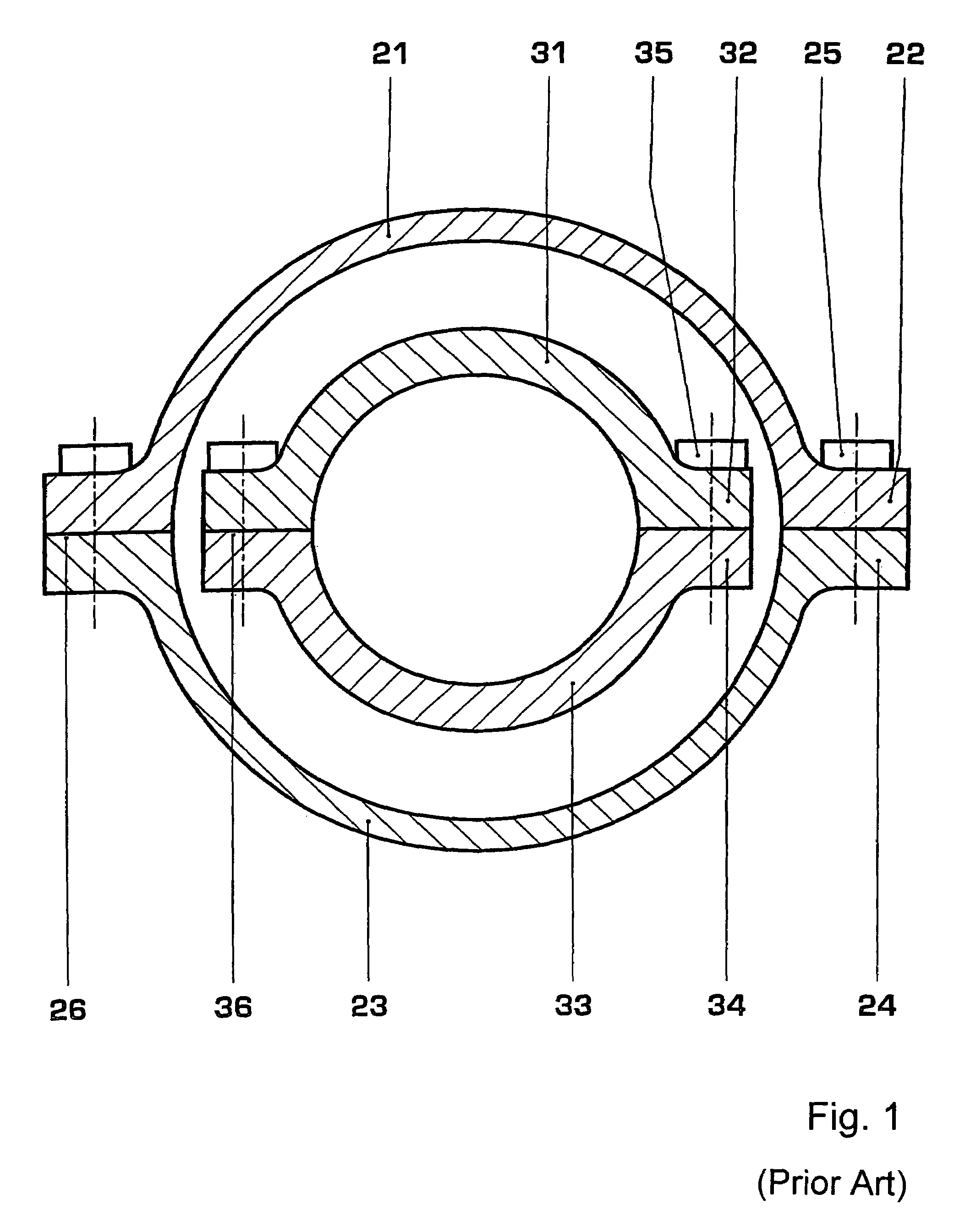
[0040]FIG. 1 is described above in connection with the state of the art.

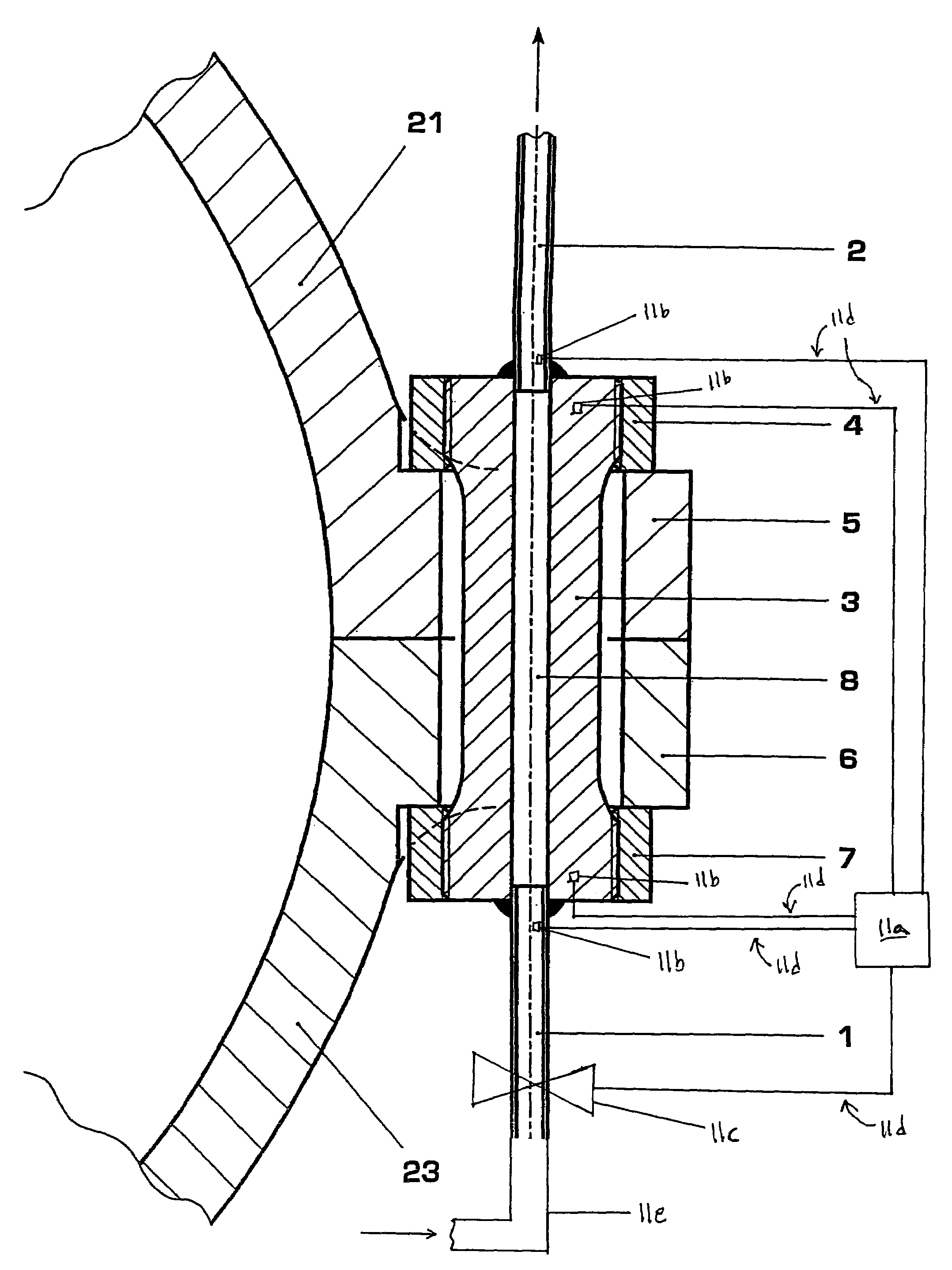
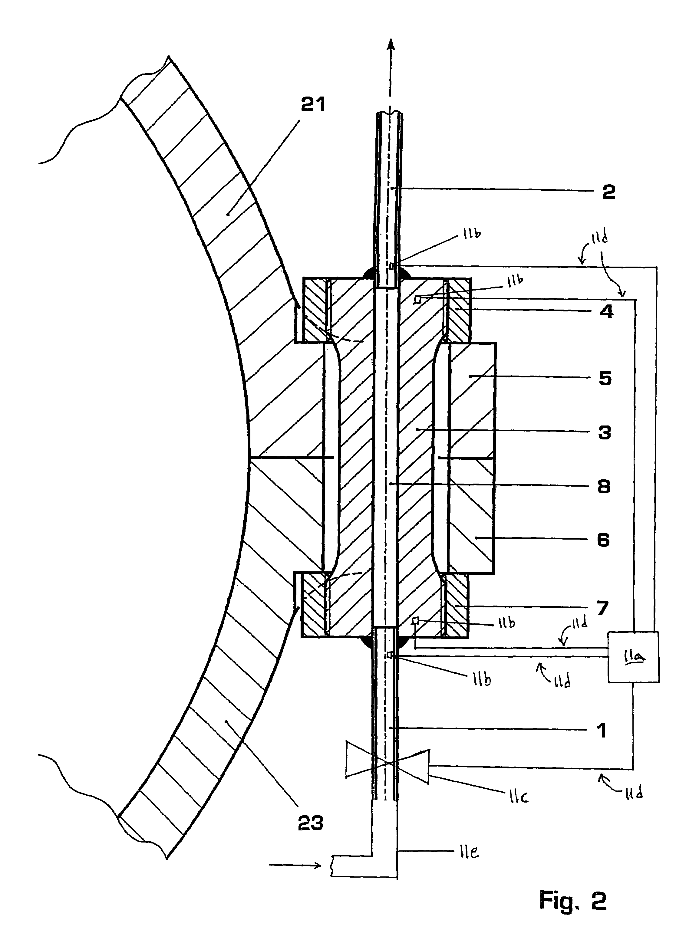
[0041]The following variants of the invention are disclosed in connection with a cooling medium flowing through the flange bolts. In accordance with the disclosure above, all of these descriptions may also be understood in connection with a heating medium. The arrangements shown in FIGS. 2–7 are for a bolt in a flange pressing together the two halves of a turbine casing. In all cases this casing can be either an outer or inner turbine casing. FIG. 2 shows in cross-section an upper and lower flange part 5 and 6 arranged to press together the upper and lower halves 21, 23 of an outer turbine casing with a bolt 3 and upper and lower nuts 4 and 7, respectively.

[0042]In all the variants of the arrangement according to the invention.

[0043]The arrangement for the cooling of the bolt, according to the preferred embodiment of the invention, comprises a borehole 8 extending along the longitudinal axis.

[0044]An inlet pipe ...


PUM


Abstract

An arrangement for cooling or heating of a flange bolt for turbines comprises one or more boreholes, that extend through the bolt, and inlet and outlet pipes that are connected to each end of the borehole. A cooling or heating medium such as air, steam or any other fluid flows through an inlet pipe into and through the borehole thereby cooling or heating the bolt, and exits from the borehole via an outlet pipe. The cooling or heating arrangement enables direct cooling or heating of the bolt itself and ensures stable bolting forces throughout the operation of the turbine. The flange bolts with this arrangement may be applied to gas turbines or steam turbines operated at elevated steam temperatures and pressures.

Description

[0001]This application claims priority under 35 U.S.C. § 119 to U.S. Provisional Application No. 60 / 365,620 entitled Flange Bolt for Turbines and filed on Mar. 20, 2002, the entire content of which is hereby incorporated by reference.FIELD OF THE INVENTION[0002]The invention pertains to flange bolts applied to turbines and in particular to an arrangement for cooling and heating of such flange bolts and to a control system for operating the arrangement.BACKGROUND OF THE INVENTION[0003]Flange bolts are used to press together various components of a turbine, as for example a turbine casing, pipes or other joints.[0004]A turbine casing comprises flanges that are integral parts of the casing and intended to hold together the upper and lower halves of the casing when it is under pressure. One half of the casing comprises an upper flange half and the other half a lower flange half, which are pressed together by flange bolts and flange nuts. The two flange halves are pressed together by mea...

Claims


Application Information

Patent Timeline
Patent Type & Authority Patents(United States)
IPC IPC(8): F01D25/10F01D25/12F01D25/24
CPCF01D25/243Y10T403/645Y10T403/25Y10T403/648Y10T403/255Y10T403/64Y10T403/17F16B2200/50F16B2200/506F16B2200/509
Inventor REIGL, MARTIN
Owner GENERAL ELECTRIC TECH GMBH
Why Eureka
Try Eureka