Device for blow-molding containers

a technology for blow molding and containers, applied in the direction of dough shaping, manufacturing tools, food shaping, etc., can solve the problem of relatively labor-intensive corresponding change of base extension

Inactive Publication Date: 2006-05-02
KHS GMBH
View PDF14 Cites 33 Cited by
  • Summary
  • Abstract
  • Description
  • Claims
  • Application Information

AI Technical Summary

Benefits of technology

[0023]Another feature that contributes to ensuring security against tipping over is that the

Problems solved by technology

The corresponding change of the base extension is relatively labor intensive because of the screw fitting that is provi

Method used


Image

  • Device for blow-molding containers
  • Device for blow-molding containers
  • Device for blow-molding containers

Examples


Embodiment Construction

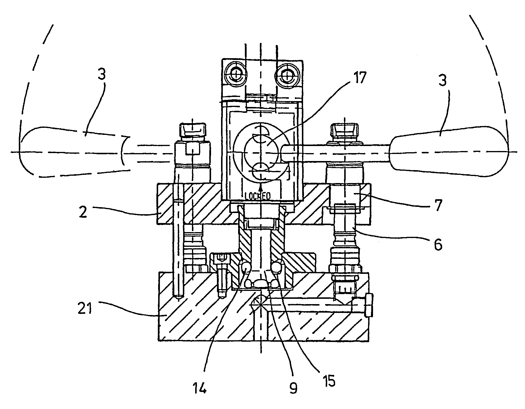
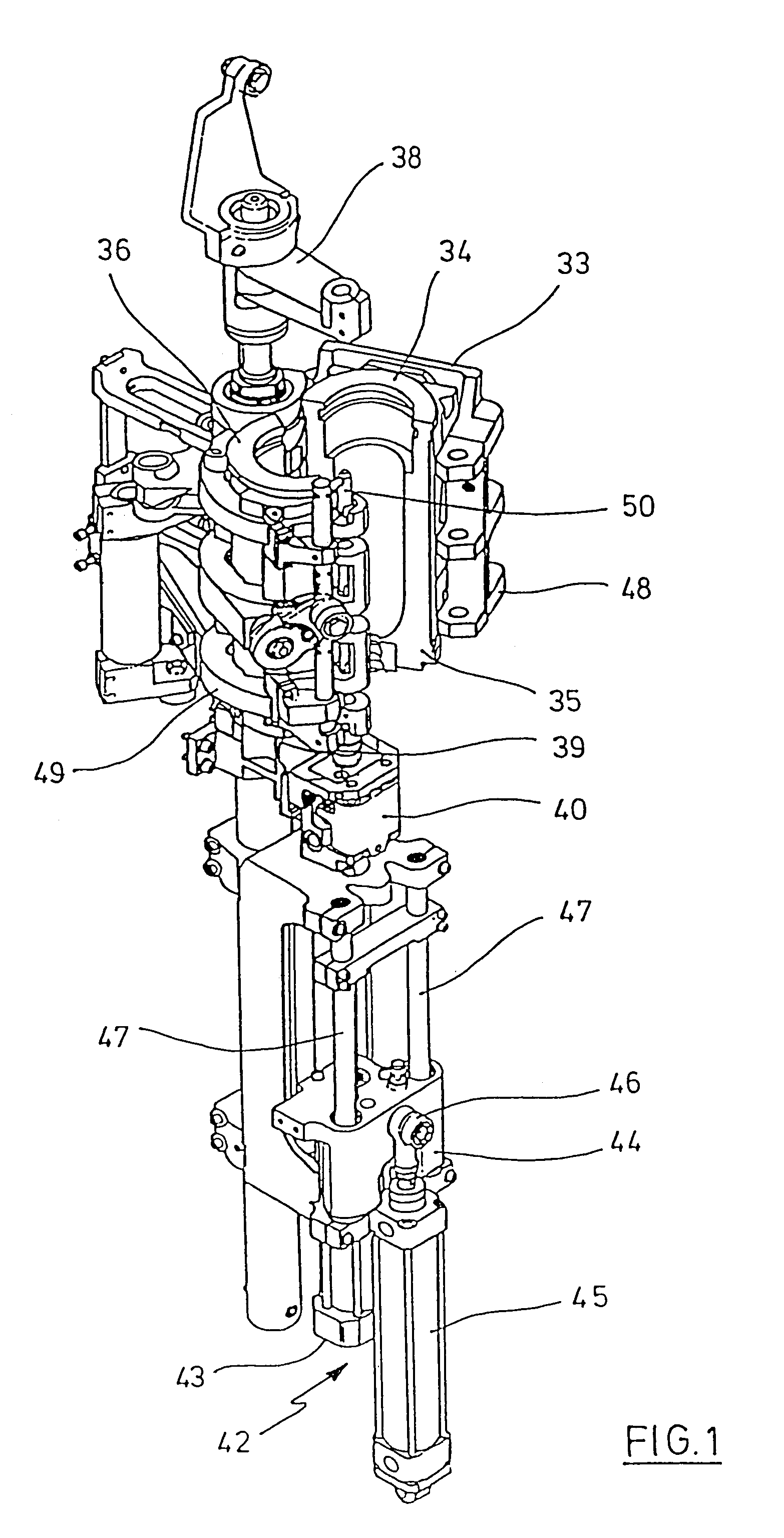
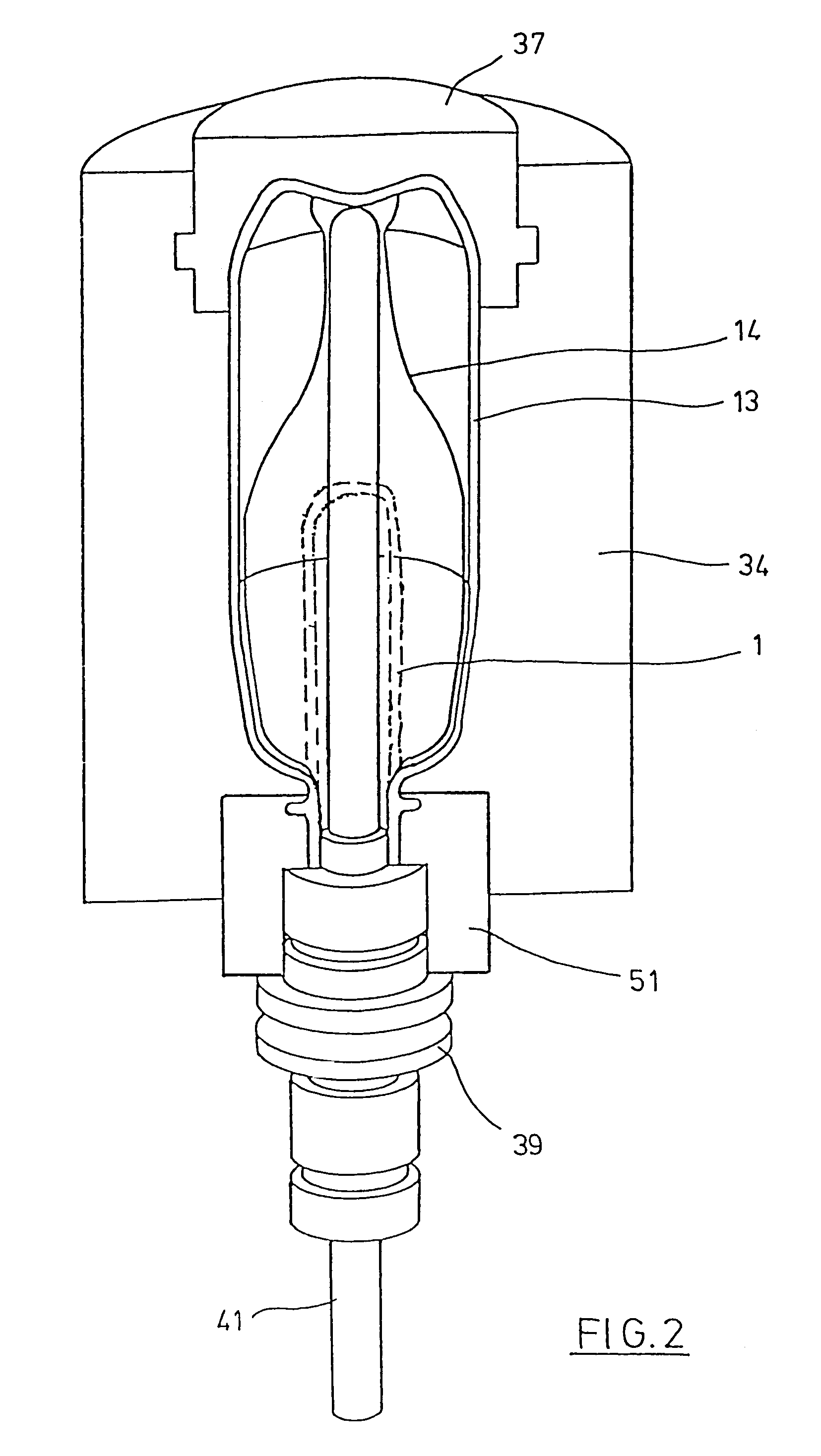
[0033]The basic structure of a device for the reshaping of pre-molded elements (1) into containers (13) is illustrated in FIG. 1 and FIG. 2.

[0034]The device for molding the container (13) includes, in essence, a blowing station (33), which is provided with a blow mold (34), into which a pre-molded element (1) is capable of being inserted. The pre-molded element (1) can be an injection molded component including poly(ethylene terephthalate). In order to permit the insertion of the pre-molded element (1) into the blow mold (34), and in order to permit the removal of the finished container, the blow mold (34) includes blow mold segments (35, 36) and a base extension (37) that is capable of being positioned by a lifting device (38). The pre-molded element (1) can be supported by a transport mandrel (39) in the region of the blowing station (33), wherein the transport mandrel, along with the pre-molded element (1), passes through a plurality of treatment stations inside the device. Howev...


PUM

PropertyMeasurementUnit
Distanceaaaaaaaaaa

Abstract

The device serves for the blow molding of containers that comprise a thermoplastic material, wherein the device has at least one blowing station with at least one blow mold. The blow mold is formed from at least two blow mold segments that are supported by supports, wherein the blow mold has a base extension. The base extension is arranged in such a way that it is capable of being positioned in the direction of a longitudinal axis of the blow mold, and is supported by a base plate. The base plate connects the base extension to a positioning device. The base plate is additionally connected to the base extension by a profiled coupling section, wherein this profiled coupling section is formed from a coupling element, which is connected to the base plate, along with a counter element that is connected to the base extension. The profiled coupling section is capable of being actuated via a manual lever. At least two hollow coupling plugs are arranged a certain distance from the profiled coupling section, wherein these coupling plugs are capable of being introduced into self-sealing coupling sockets.

Description

[0001]This application is the national phase under 35 U.S.C. § 371 of PCT International Application No. PCT / DE01 / 02395 which has an International filing date of Jul. 6, 2001, which designated the United States of America and which claims priority on German Patent Application number DE 100 33 412.1 filed Jul. 8, 2000, the entire contents of which are hereby incorporated herein by reference.FIELD OF THE INVENTION[0002]The invention generally pertains to a device for the blow molding of containers. Preferably, it pertains to one that includes a thermoplastic material, wherein the device has at least one blowing station with at least one blow mold, which is formed from at least two blow mold segments that are supported by supports. More preferably, the blow mold has a base extension that is arranged in such a way that it is capable of being positioned in the direction of a longitudinal axis of the blow mold, and even more preferably, the base extension is supported by a base plate that ...

Claims


Application Information

Patent Timeline
IPC IPC(8): B29C49/64B29C33/30B29C49/06B29C49/54
CPCB29C33/306B29C49/541B29C49/06B29K2067/00B29C2049/4858B29C2949/0715
Inventor LINKE, MICHAELMUELLER, HARTWIGGERHARDS, MARTINLITZENBERG, MICHAEL
Owner KHS GMBH
Why Eureka
Try Eureka