
Oar

Inactive Publication Date: 2006-05-02
FAN PO HSUN
View PDF7 Cites 4 Cited by
  • Summary
  • Abstract
  • Description
  • Claims
  • Application Information

AI Technical Summary

Benefits of technology

[0006]The primary purpose of the present invention is to provide an oar, which enhances the rowing efficiency by: increasing the pressure bearing surface of the blade when rowing the oar against the water and reducing the pressure bearing surface of the blade when lifting the oar from the water. According to one aspect of the present invention, the oar comprises a shaft, a fixed blade axially extending from one end of the shaft, and a supplementary blade pivotally connected to the connection area between the blade and the shaft and turns relative to the fixed blade between a received position and an extended position. The supplementary blade is received to the fixed blade without increasing the water resisting force when the user lifts the oar from the water during rowing. The supplementary blade is turned outwards from the fixed blade to the extended position to increase the pressure bearing surface (water expelling surface) of the oar, when the user rowing the oar against the water, thereby enhancing the rowing efficiency. According to another aspect of the present invention, a constraint member is provided to limit the turning angle of the supplementary blade relative to the fixed blade to a predetermined range. Preferably, the turning angle is within 90°˜180°. The constraint member can be a soft cord member connected between the fixed blade and the supplementary blade. Alternatively, the constraint member can be a stop rod fixedly provided at the connection area between the fixed blade and the shaft.

Problems solved by technology

However, it requires much effort to row an oar having a relatively greater blade surface area.

Method used


Image

  • Oar
  • Oar
  • Oar

Examples


Embodiment Construction

[0013]The following descriptions are of exemplary embodiments only, and are not intended to limit the scope, applicability or configuration of the invention in any way. Rather, the following description provides a convenient illustration for implementing exemplary embodiments of the invention. Various changes to the described embodiments may be made in the function and arrangement of the elements described without departing from the scope of the invention as set forth in the appended claims.

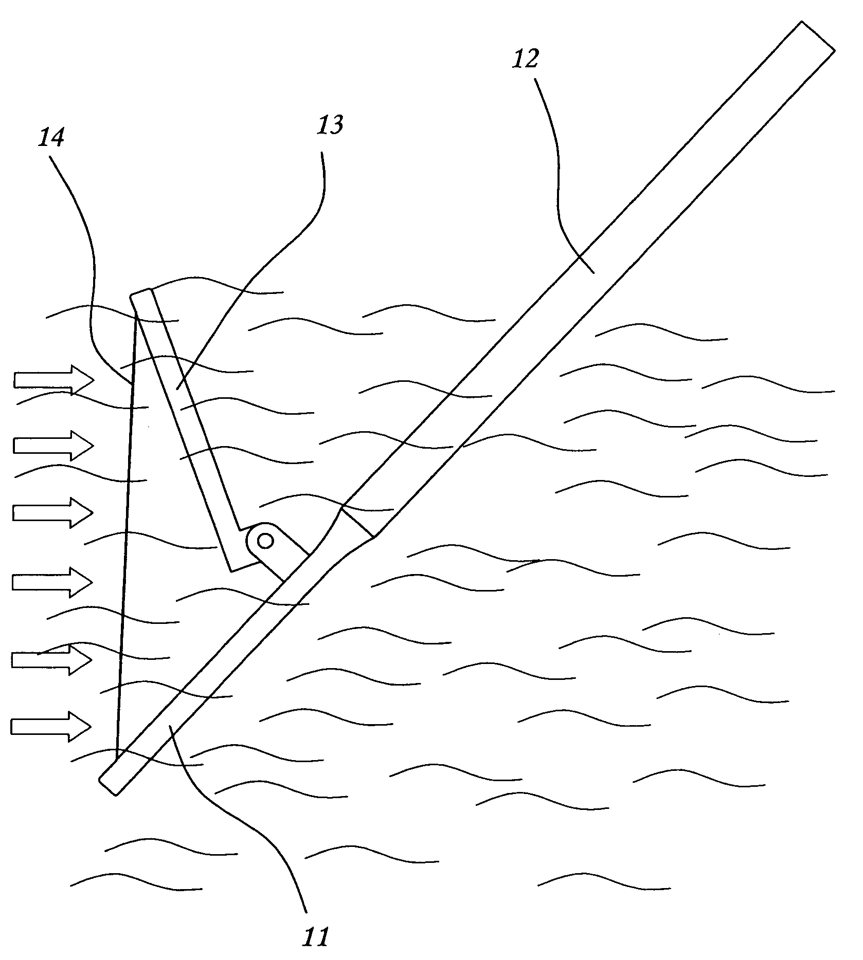
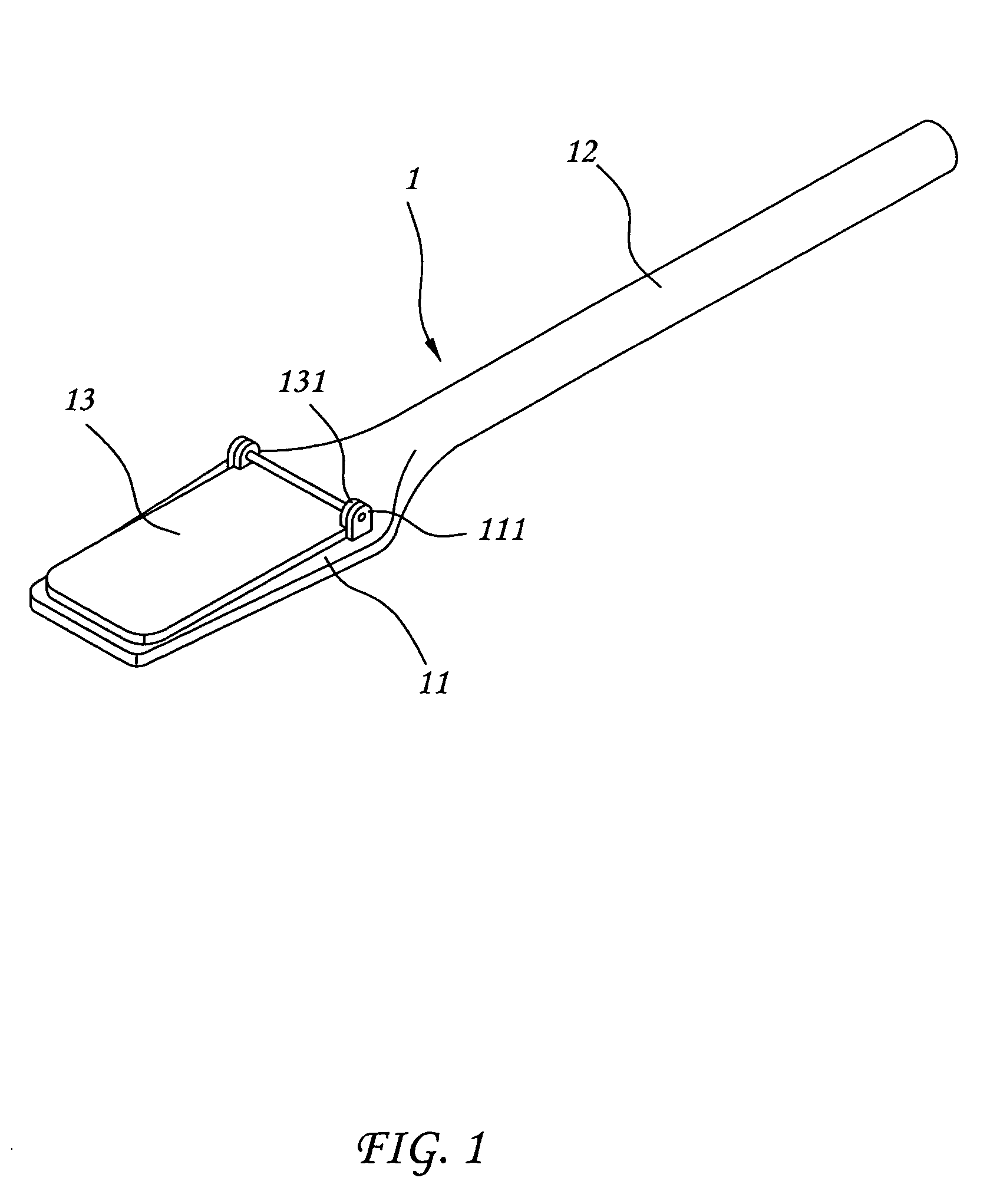
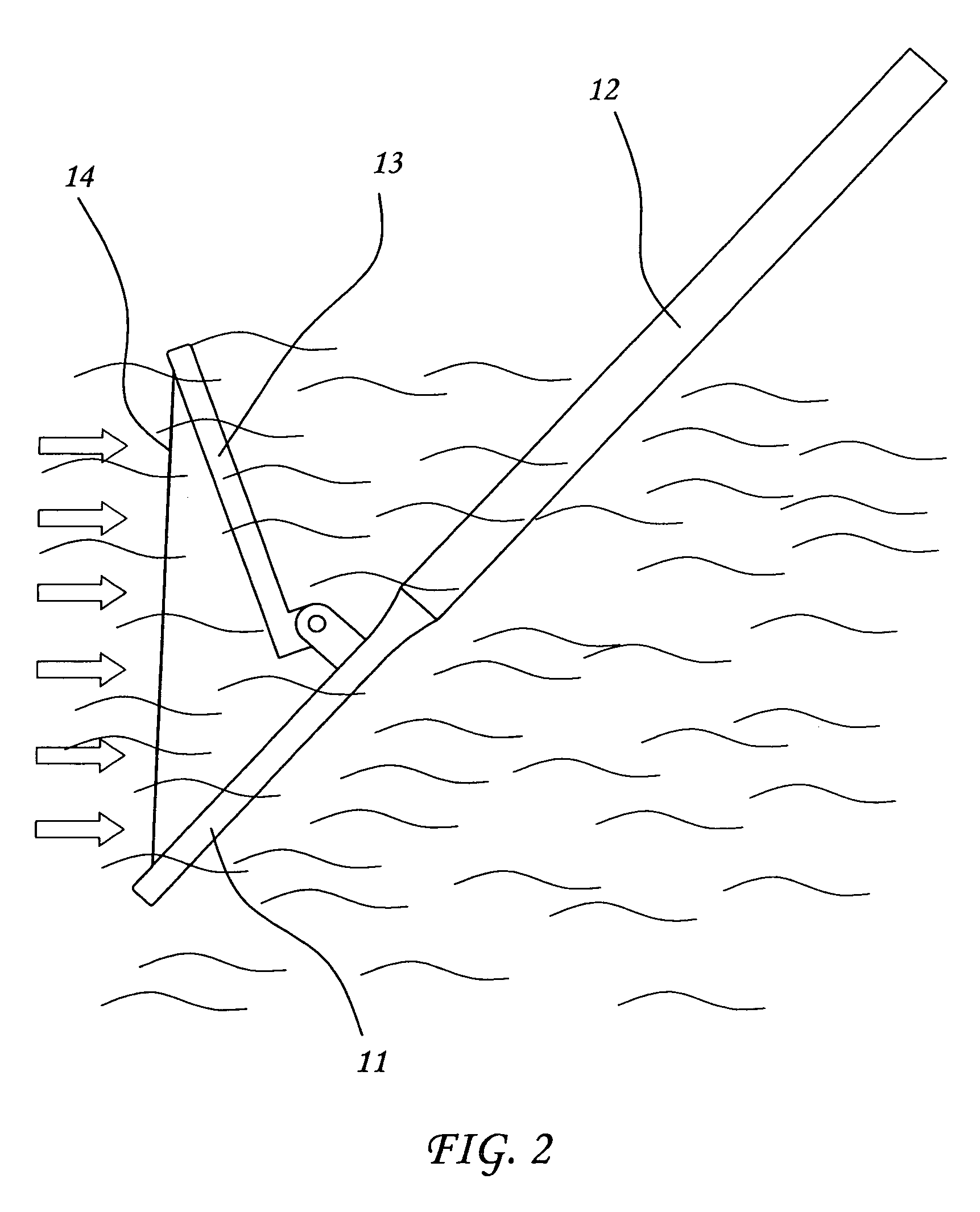
[0014]Referring to FIG. 1, an oar 1 in accordance with the present invention is shown comprising a shaft 12, a fixed main blade 11 extended from one end, namely, the bottom end of the shaft 12, and a movable supplementary blade 13 pivotally connected to the main blade 11 adjacent to the shaft 12. The supplementary blade 13 can be turned between a received position where the contained angle between the main blade 11 and the supplementary blade 13 is zero, and an extended position where the contain...


PUM


Abstract

Disclosed is an oar, which has a supplementary blade pivotally connected to one end of the blade adjacent to the shaft thereof to increase the area of the water expelling surface, enhancing the rowing efficiency.

Description

BACKGROUND OF THE INVENTION[0001](a) Technical Field of the Invention[0002]The present invention relates to an oar for rowboat and more particularly, to such an oar, which is equipped with a pivoted supplementary blade to enhance the rowing.[0003](b) Description of the Prior Art[0004]When rowing a rowboat, an oar or two oars shall be used. An oar for this purpose comprises a shaft, a grip fixedly provided at one end of the shaft, and a flat blade fixedly provided at the other end of the shaft. For comfortable gripping of the hand, the grip of an oar is made in a cylindrical shape. When rowing a rowboat, the user who sits in the rowboat must insert the blade of the oar into the water and then move the oar to force the blade against the water, and then lift the oar from the water, and then repeat the rowing procedure again and again. When forcing the blade against the water, a resisting force is produced to move the rowboat on the water.[0005]A person who learned fluid mechanics or me...

Claims


Application Information

Patent Timeline
IPC IPC(8): B63H16/04
CPCB63H16/04
Inventor FAN, PO-HSUN
Owner FAN PO HSUN
Features
  • Generate Ideas
  • Intellectual Property
  • Life Sciences
  • Materials
  • Tech Scout
  • Unparalleled Data Quality
  • Higher Quality Content
  • 60% Fewer Hallucinations
Learn More