Joining member for mechanically joining a skin to a supporting rib

a technology of supporting ribs and joining members, which is applied in the field of structural members, can solve the problems of difficult and therefore labor-intensive construction of such structural members, difficult alignment, and a substantial amount of time even when possible, and achieve the effect of reducing the risk of separation and being less expensiv

Inactive Publication Date: 2006-05-02
ROGERS TERRY W +1
View PDF20 Cites 71 Cited by
  • Summary
  • Abstract
  • Description
  • Claims
  • Application Information

AI Technical Summary

Benefits of technology

[0012]Another objective is to provide a joining member for mechanically joining a skin to a supporting rib using a method that is faster, easier, less expensive, and more relia

Problems solved by technology

Construction of such structural members is difficult and therefore labor intensive.
Such precise alignment is difficult to achieve, and takes a substantial amount of time even when possible.
However, the

Method used


Image

  • Joining member for mechanically joining a skin to a supporting rib
  • Joining member for mechanically joining a skin to a supporting rib
  • Joining member for mechanically joining a skin to a supporting rib

Examples


Embodiment Construction

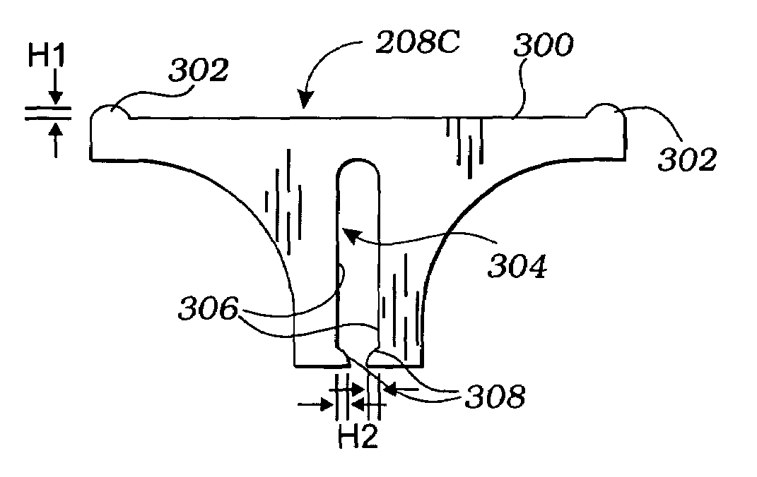
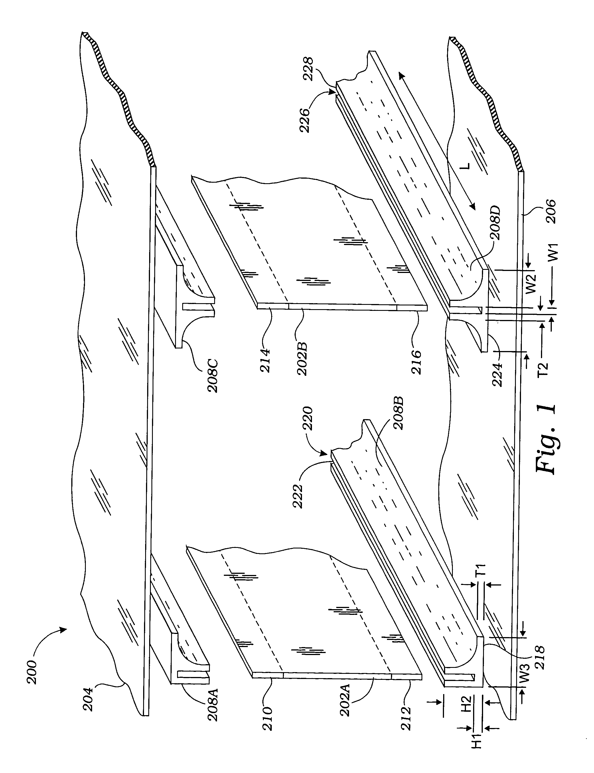
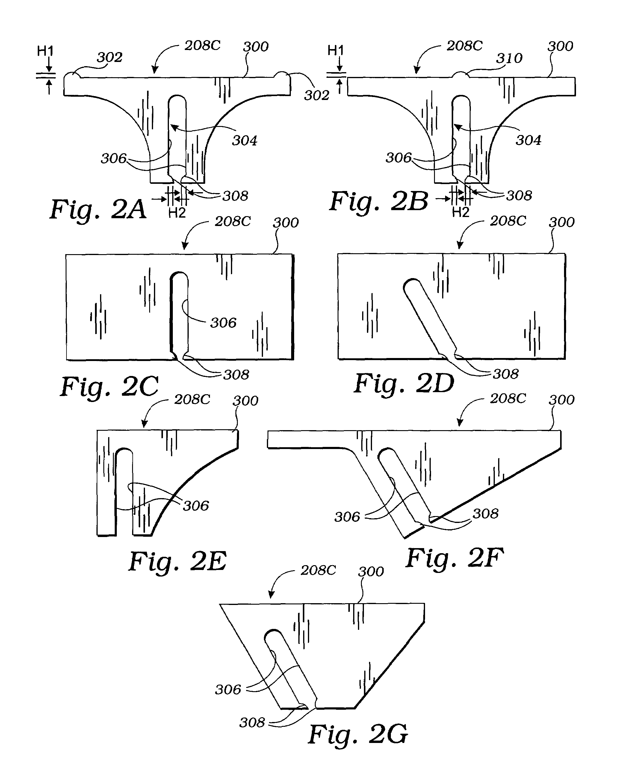
[0025]FIG. 1 is an exploded perspective view of a section 200 of a structural element illustrating relative positions of several components. The structural element may be any structure that includes a skin that is or may be supported by a rib, including a variety of walls, tanks, airfoils, bulkheads, ramps, or other structural elements. Since the particular application of this technology is not important, the application should not be limited the construction of the below-described claims.

[0026]As shown in FIG. 1, in the section 200, ribs 202A and 202B are adapted for supporting an upper skin 204 and a lower skin 206 are shown positioned between the upper skin 204 and the lower skin 206. A joining member 208A is positioned between an upper edge 210 of the rib 202A and the upper skin 204, and is used to connect the upper edge 210 of the rib 202A to the upper skin 204. A joining member 208B is positioned between a lower edge 212 of the rib 202A and the lower skin 206, and is used to c...


PUM

PropertyMeasurementUnit
Thicknessaaaaaaaaaa

Abstract

A joining member for mechanically joining a skin to a supporting rib has a first surface and a second surface opposite the first surface. The first surface is adapted for bonding to a surface of the skin via a layer of a first adhesive material. The second surface includes a groove having an inner surface adapted for receiving and bonding to an outer edge of the rib via a layer of a second adhesive material. The joining member enables a novel method of construction having advantages over the prior art.

Description

BACKGROUND OF THE INVENTION[0001]1. Field of the Invention[0002]This invention relates generally to structural members, and more particularly to a joining member for mechanically joining a skin to a supporting rib.[0003]2. Description of Related Art[0004]Structural elements for supporting a skin with a rib are known in the art, particularly in the field of aircraft construction, but also in other fields. For example, U.S. Pat. No. 2,218,122 to Scheller et al. describes a structural member for supporting opposing skins of an airplane control element (e.g., wing). The structural member includes one or more web sections riveted between flange scarfs. Each flange scarf includes either a “T”-shaped, two “L”-shaped, or a “U”-shaped rod. Surfaces of the flange scarfs opposite the web sections extend in parallel to the wing covering.[0005]Construction of such structural members is difficult and therefore labor intensive. For example, corresponding holes must be drilled in the central web se...

Claims


Application Information

Patent Timeline
IPC IPC(8): B32B3/06
CPCB29C65/5057B29C66/221B29C66/4344B29C66/43441B29C66/721B32B7/04B64C3/26B29C65/5085B29C66/438B29C66/5346B29C65/5071Y10T428/24479B29K2063/00B29K2277/10B29K2307/00B29K2309/08B29L2031/3085B29C65/485Y10T428/2457Y10T428/24174B29C66/7212B29C66/71B29C65/7829B29C66/112B29C66/1122B29C66/1142B29C66/12441B29C66/131B29K2307/04
Inventor ROGERS, TERRY W.OLSON, WARD M.
Owner ROGERS TERRY W
Why Eureka
Try Eureka