Rotary knob assembly for home appliance

a technology of rotary knobs and knobs, applied in the field of home appliances, can solve the problems of insufficient support of rotary switches by substrates or panels, inability to stably support rotary switches, and easy destruction of rotary switches, etc., and achieve the effect of stably and accurately rotating

Active Publication Date: 2006-05-02
LG ELECTRONICS INC
View PDF23 Cites 19 Cited by
  • Summary
  • Abstract
  • Description
  • Claims
  • Application Information

AI Technical Summary

Benefits of technology

[0013]The support member supports the rotary switch such that the rotary switch is not damaged by a force applied to a side surface thereof. Moreover, the support member may provide support for the rotary switch and the knob, alternatively, the support member may provide support for either the rotary switch or the knob. Further, the support member is formed normal to the side surface of the rotary switch, and is formed to enclose at least a portion of the rotary switch.
[0019]According to the present invention, since the rotary switch is stably supported, the encoder is not damaged or the shaft is not deformed. Further, the knob can be stably and accurately rotated.

Problems solved by technology

However, a heavy and large knob is directly coupled to the rotary switch, and the rotary switch is not enough supported by the substrate or the panel.
Accordingly, if a great force is applied to the home appliance or the knob assembly, the rotary switch is easily destroyed.
Further, due to the same reason, the knob is not stably supported by the rotary switch.
Accordingly, since the knob is greatly shaken left and right, it is erroneously manipulated.

Method used


Image

  • Rotary knob assembly for home appliance
  • Rotary knob assembly for home appliance
  • Rotary knob assembly for home appliance

Examples


Embodiment Construction

[0027]Reference will now be made in detail to the preferred embodiments of the present invention, examples of which are illustrated in the accompanying drawings. Wherever possible, the same reference numbers will be used throughout the drawings to refer to the same or like parts.

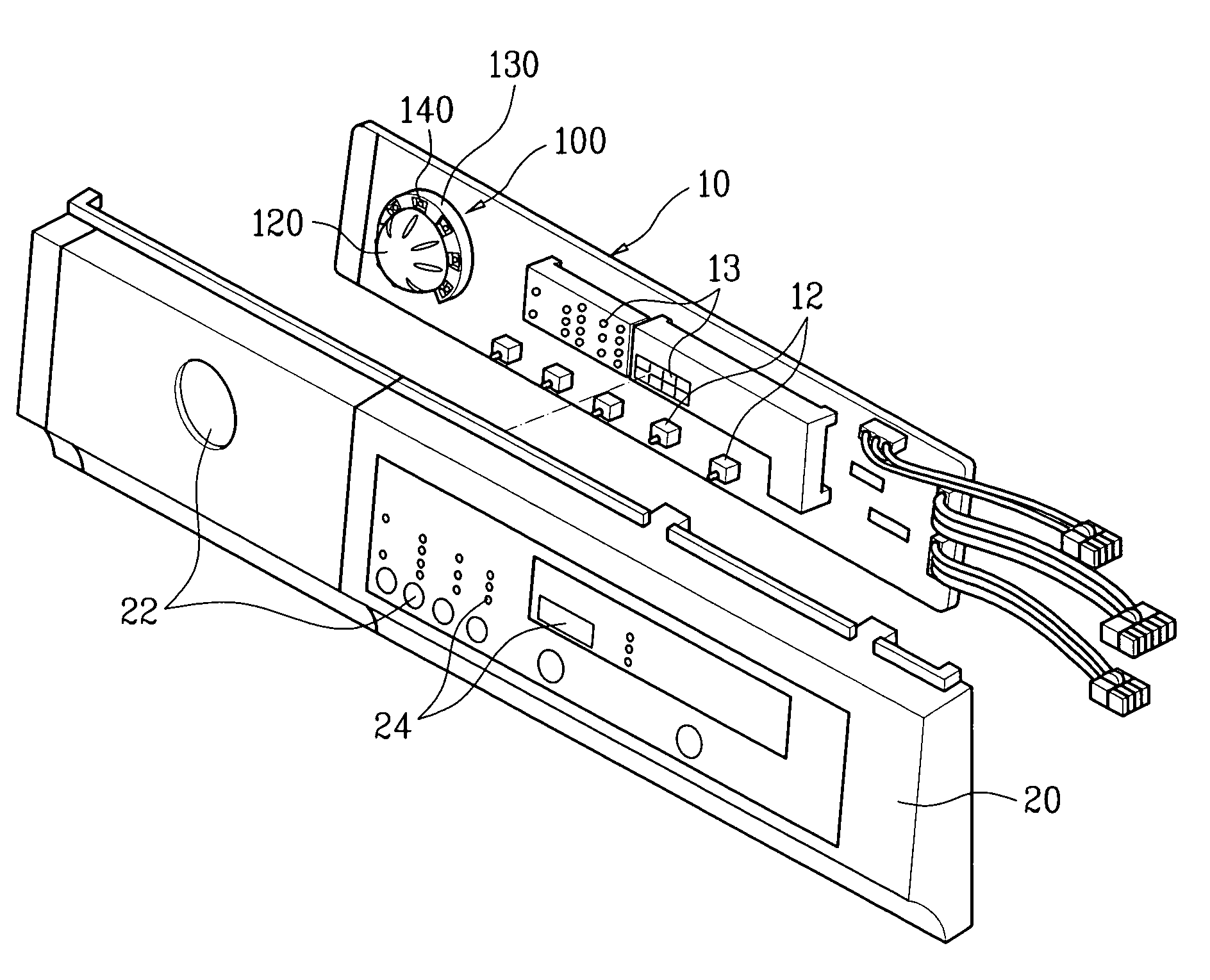
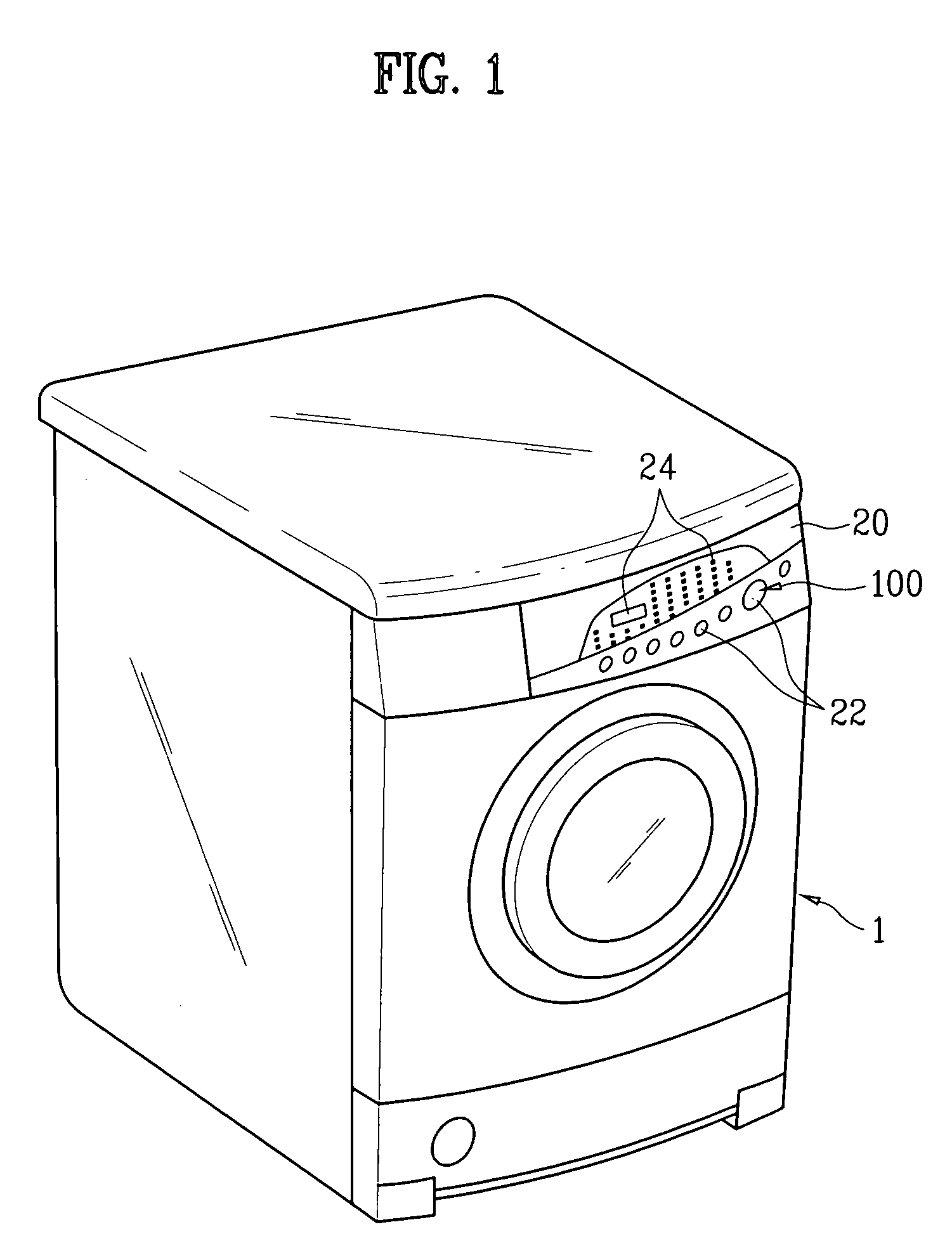
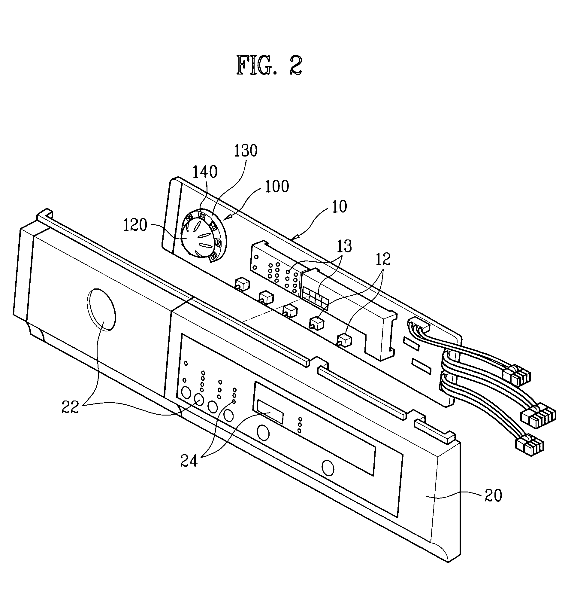
[0028]FIG. 1 is a perspective view illustrating a control panel assembly including a rotary knob assembly and a home appliance according to the present invention, and FIG. 2 is a disassembled perspective view illustrating a control panel assembly of FIG. 1. As known to the related art, in the rotary knob assembly, only a size and shape is generally varied depending on a kind of a home appliance. Accordingly, the present invention is described with reference to an embodiment applied to a washing machine as follows for description convenience, but can be identically applied to other home appliances.

[0029]FIG. 1 illustrates a generally washing machine 1. Generally, a washing machine performs washing, rinsing an...


PUM


Abstract

Disclosed is a rotary knob assembly for a home appliance. The assembly includes a rotary switch having an encoder and a shaft rotatably installed at the encoder, a knob coupled to the shaft of the rotary switch, and a support member provided around the rotary switch to support the rotary switch.

Description

[0001]This application claims the benefit of Korean Applications No. P2003-0059520, filed on Aug. 27, 2003, and No. P2003-0059521, filed on Aug. 27, 2003, which are hereby incorporated by reference.BACKGROUND OF THE INVENTION[0002]1. Field of the Invention[0003]The present invention relates to a home appliance, and more particularly, to a rotary knob assembly mounted at a control panel of a home appliance.[0004]2. Discussion of the Related Art[0005]Generally, a home appliance includes a control panel assembly. The control panel assembly is used to instruct an operation and display an operation state of the home appliance. The control panel assembly is comprised of a panel part exposed to a user and a substrate housed within the panel part. The substrate has a switch electrically connected with a controlling unit and a display device for displaying an operation state, which are installed thereat. Various mechanical switches are provided at the panel part to operate the electric switc...

Claims


Application Information

Patent Timeline
Patent Type & Authority Patents(United States)
IPC IPC(8): H01H15/02H01H19/02H01H19/04
CPCH01H19/04H01H19/025
Inventor KIM, SHINLEE, BONG SANG
Owner LG ELECTRONICS INC
Why Eureka
Try Eureka