
Probe apparatus with laser guiding for locating a source of radioactivity

a laser guide and laser guide technology, applied in the field of laser guide device for locating the location of radioactive objects, can solve the problems of ineffective source identification, victim may receive a debilitating or fatal dose of radiation in a relatively short amount of time, and the source represents an acute exposure risk for the victim,

Active Publication Date: 2006-05-02
RGT UNIV OF CALIFORNIA
View PDF16 Cites 13 Cited by
  • Summary
  • Abstract
  • Description
  • Claims
  • Application Information

AI Technical Summary

Benefits of technology

The invention is a radiation probe that can visually locate a source of gamma radiation. It includes a lead collimator with a pinhole at its distal end, a means for detecting radiation, and a laser emitter positioned in the collimator. The probe can also have a housing, a battery pack, and a removable sleeve to change the size of the pinhole. The invention can be used in various applications such as detecting radiation in a suspected area or in a person.

Problems solved by technology

These HASA sources represent an acute exposure risk to the victim, emergency responders and medical personnel due to high levels of gamma radiation emitted.
If not removed quickly, the victim may receive a debilitating or fatal dose of radiation in a relatively short amount of time.
Further, the level of radiation emitted from a HASA source would register off the scale and potentially damage radiation detection / imaging equipment available in a medical facility, rendering them ineffective for pinpointing the source.
Emergency responders and medical personnel are at risk of overexposure to radiation when in close proximity to victims with embedded HASA sources.
Without a quick and efficient method to pinpoint HASA sources, a victim would be subject to excess tissue debridement, trauma or amputation to ensure immediate removal of radioactive shrapnel from the body.

Method used


Image

  • Probe apparatus with laser guiding for locating a source of radioactivity
  • Probe apparatus with laser guiding for locating a source of radioactivity
  • Probe apparatus with laser guiding for locating a source of radioactivity

Examples


Embodiment Construction

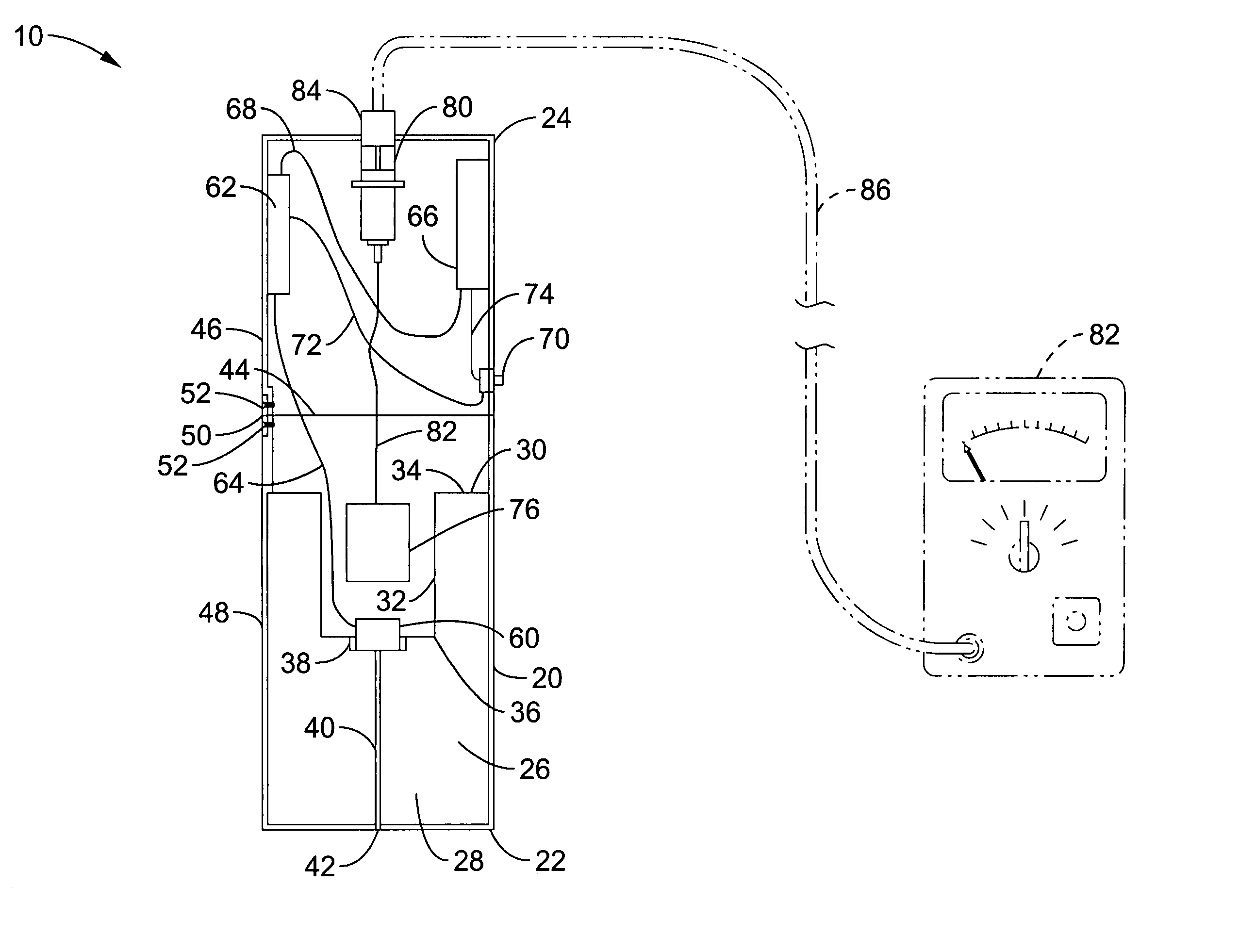
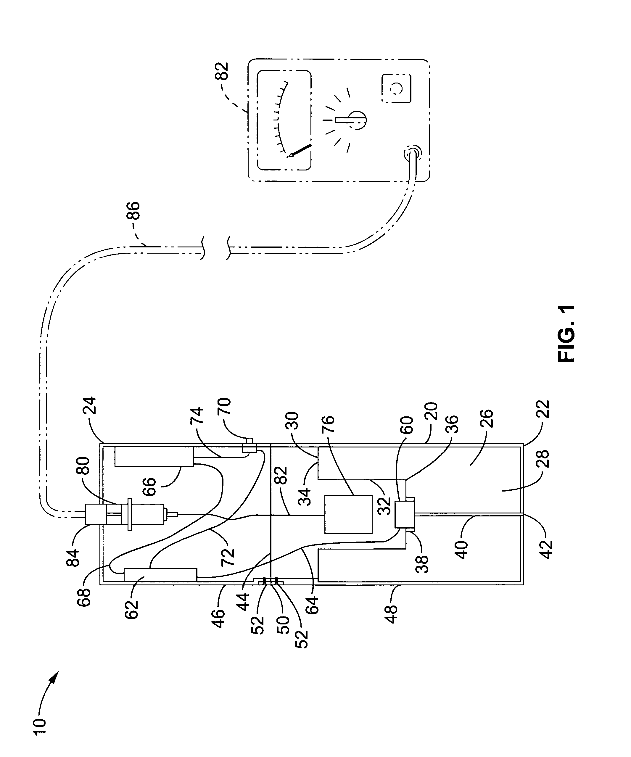
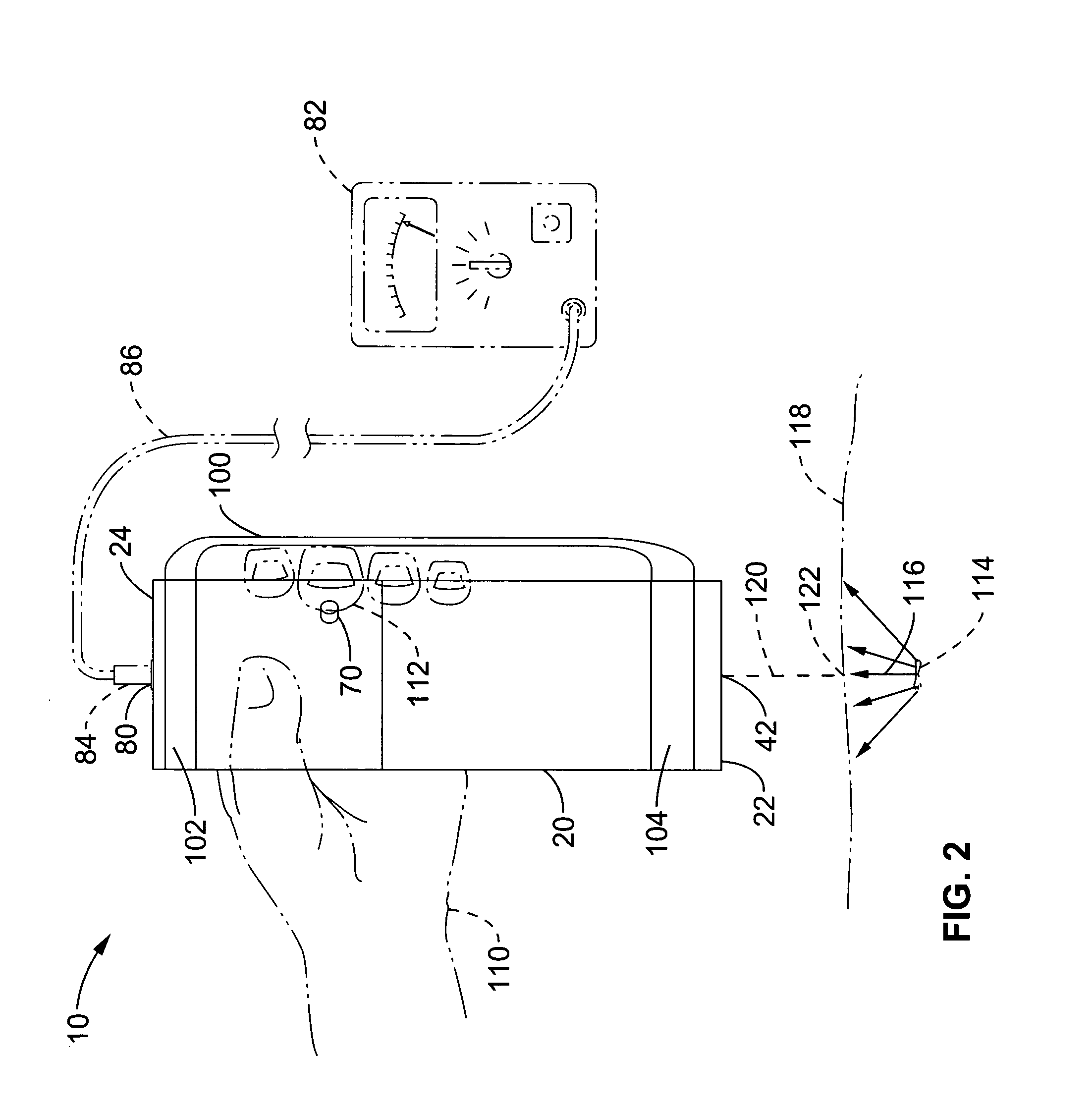
[0054]Referring more specifically to the drawings, for illustrative purposes the present invention is embodied in the apparatus generally shown in FIG. 1 through FIG. 9. It will be appreciated that the apparatus may vary as to configuration and as to details of the parts, and that the method may vary as to the specific steps and sequence, without departing from the basic concepts as disclosed herein.

[0055]FIG. 1 through FIG. 3 illustrate an embodiment of a wound probe with a laser beam as a guide pointer, generally designated as wound probe 10.

[0056]FIG. 1 is a cross section schematic illustration of wound probe 10. Wound probe 10 has a cylindrical housing 20 with distal end 22 and proximal end 24. Housing 20 is made of a light weight durable material such as aluminum, plastic or composite material. A cylindrical lead collimator 26 is positioned in housing 20 at distal end 22. Collimator 26 has a distal end 28, and a proximal end 30. The distal end 28 of collimator 26 is aligned wit...


PUM


Abstract

A highly directional radiation probe with a laser guide to pinpoint the position of a source of radiation. The probe is configured with a lead pinhole collimator, a radiation detector configured to detect radiation through the pinhole, and a laser positioned in the collimator and configured to project a beam through the pinhole. When the probe is aligned with the radiation source detected through the pinhole, the laser is activated and projects a beam at the source position. The probe can scan a person in three dimensions to quickly locate radioactive shrapnel for removal. The probe can also be used to pinpoint small sources of radiation in a localized area within a radius up to about 20 meters or further, depending on the level of radiation exposure encountered. The probe is adapted to be hand-held, battery-operated and used with a visual or audible radioactivity indicator or a visual display device.

Description

CROSS-REFERENCE TO RELATED APPLICATIONS[0001]This application claims priority from U.S. provisional application Ser. No. 60 / 571,417 filed on May 13, 2004, incorporated herein by reference in its entirety.STATEMENT REGARDING FEDERALLY SPONSORED RESEARCH OR DEVELOPMENT[0002]Not ApplicableINCORPORATION-BY-REFERENCE OF MATERIAL SUBMITTED ON A COMPACT DISC[0003]Not ApplicableNOTICE OF MATERIAL SUBJECT TO COPYRIGHT PROTECTION[0004]A portion of the material in this patent document is subject to copyright protection under the copyright laws of the United States and of other countries. The owner of the copyright rights has no objection to the facsimile reproduction by anyone of the patent document or the patent disclosure, as it appears in the United States Patent and Trademark Office publicly available file or records, but otherwise reserves all copyright rights whatsoever. The copyright owner does not hereby waive any of its rights to have this patent document maintained in secrecy, includ...

Claims


Application Information

Patent Timeline
Patent Type & Authority Patents(United States)
IPC IPC(8): G01T1/169G01T1/161
CPCA61B6/4258G01T1/161
Inventor BUSHBERG, JERROLD T.CASE, JAMES P.
Owner RGT UNIV OF CALIFORNIA
Learn More