
MOS varactor for LC VCOs

a voltage control and varactor technology, applied in pulse generators, pulse techniques, instruments, etc., can solve the problems of sensitivity to supply noise and supply variations, less advantageous use, and suffer from the disadvantage of not being a commonly used, well-modeled cmos device structure such as the standard nmos or pmos device, etc., to achieve good q, large c(v) range, and good q

Active Publication Date: 2006-05-02
ANALOG DEVICES INC
View PDF7 Cites 8 Cited by
  • Summary
  • Abstract
  • Description
  • Claims
  • Application Information

AI Technical Summary

Benefits of technology

The present invention is about a new type of semiconductor device called a varactor that can be used in CMOS technologies. This device has the benefits of an I-MOS device, such as a large C(V) range and good Q, but without its disadvantages like poor supply pushing and supply noise isolation. The device has a source, drain, and back gate that are all electrically separate. It can be used in a voltage controlled oscillator (VCO) and can be either an nMOS or pMOS device. Overall, this new device offers improved performance and reliability for CMOS technologies.

Problems solved by technology

Implementing monolithic voltage controlled oscillators (VCOs) in standard complementary metal oxide semiconductor (CMOS) technology is a major challenge for the design of radio-frequency (RF) CMOS transceiver integrated circuits (ICs).
One disadvantage of this mode with supply referenced VCO tanks and / or tuning voltages is a sensitivity to supply noise and supply variations (frequency pushing).
This deficiency often requires a remedy of additional supply regulation and / or large off-chip capacitor filtering that are undesirable for low power and low cost communication applications.
But, under typical large signal VCO swing operation it has less than half the tuning range, which makes it less advantageous to use.
While the A-MOS C(V) range is typically as large as an I-MOS even under large signal operation, it suffers from the disadvantage of not being a commonly used, well-modeled CMOS device structure such as the standard nMOS or pMOS devices.
As a result, the A-MOS device often is not well-controlled, reliably fabricated, or accurately modeled.

Method used


Image

  • MOS varactor for LC VCOs
  • MOS varactor for LC VCOs
  • MOS varactor for LC VCOs

Examples


Embodiment Construction

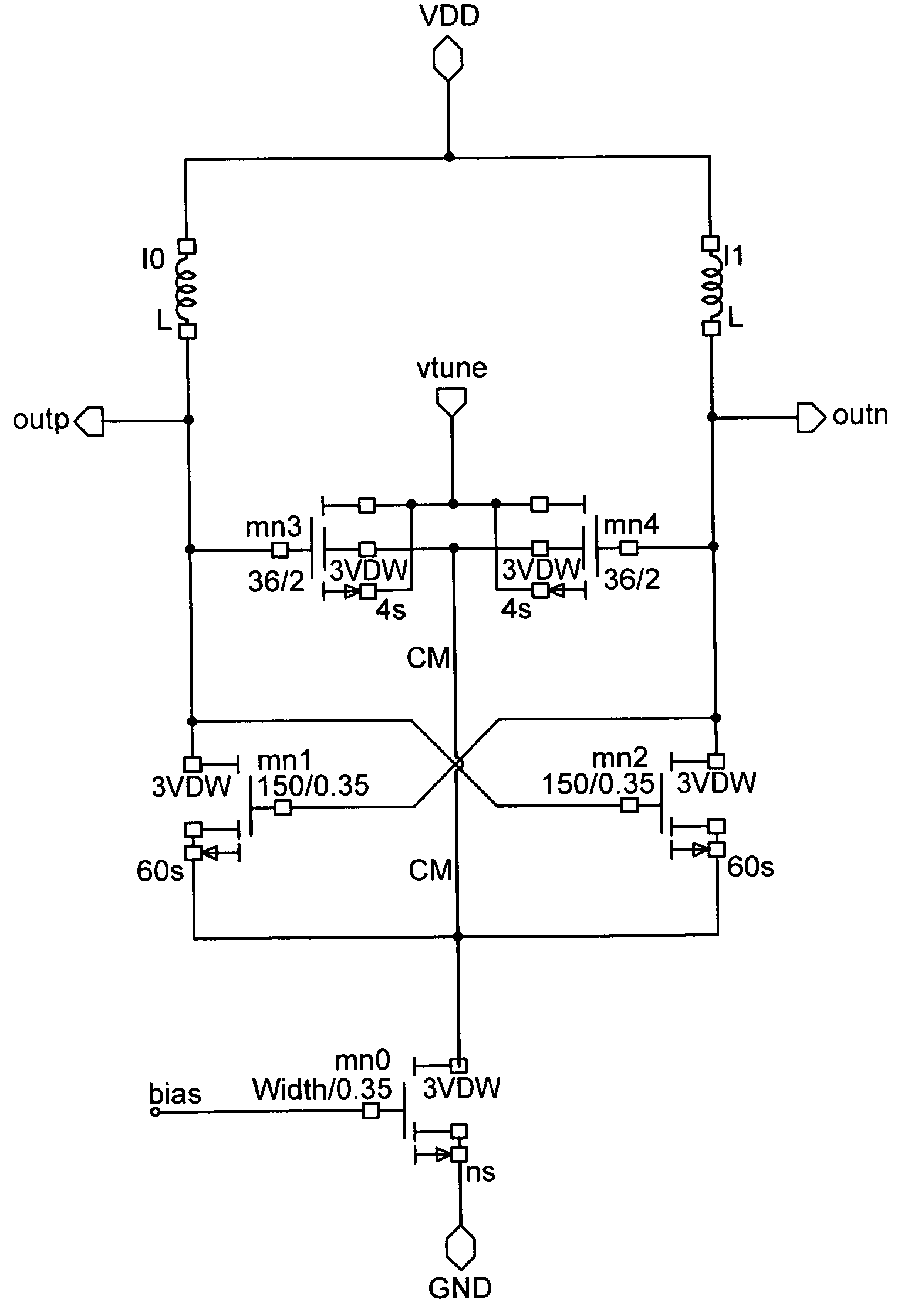
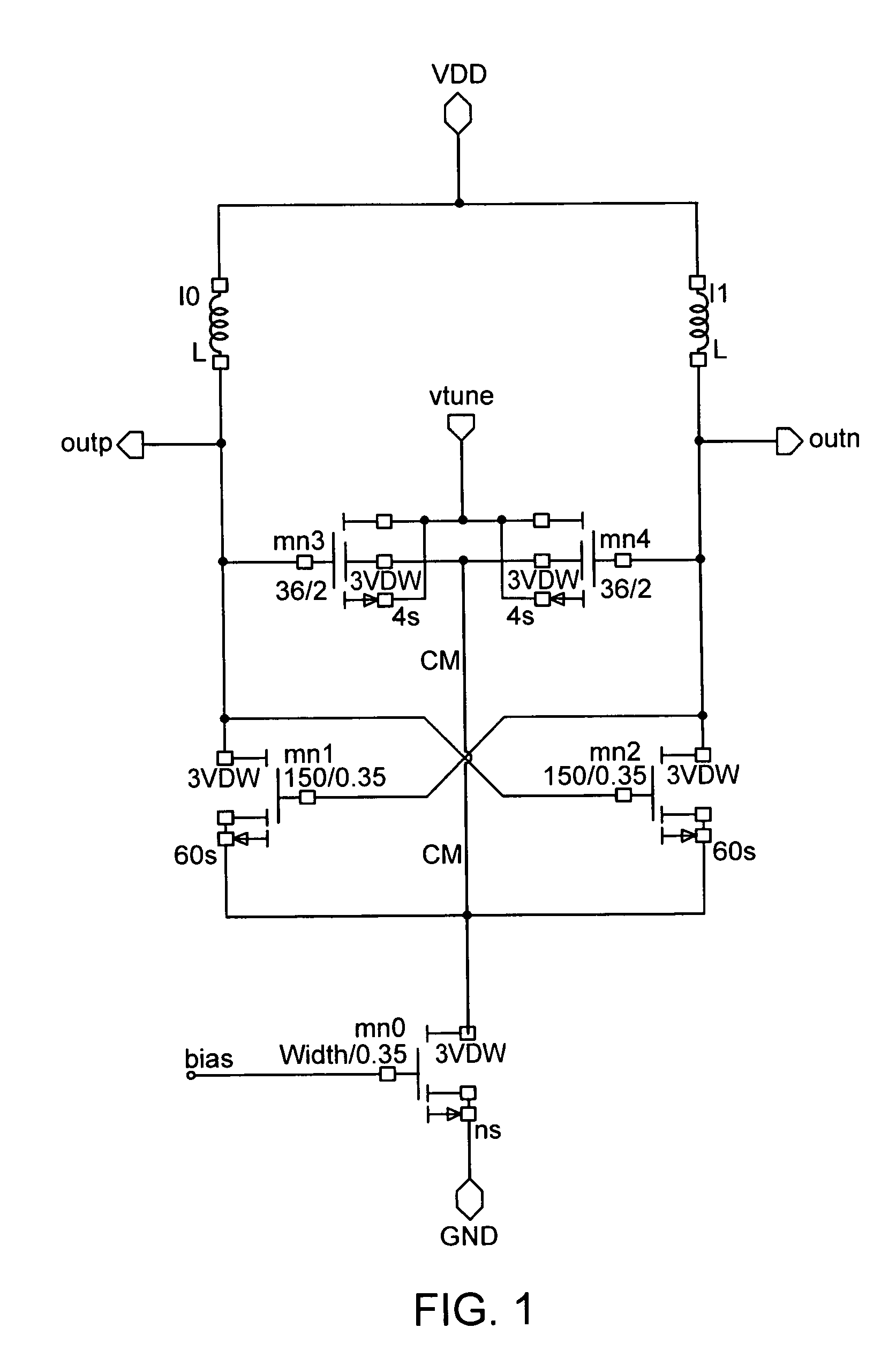
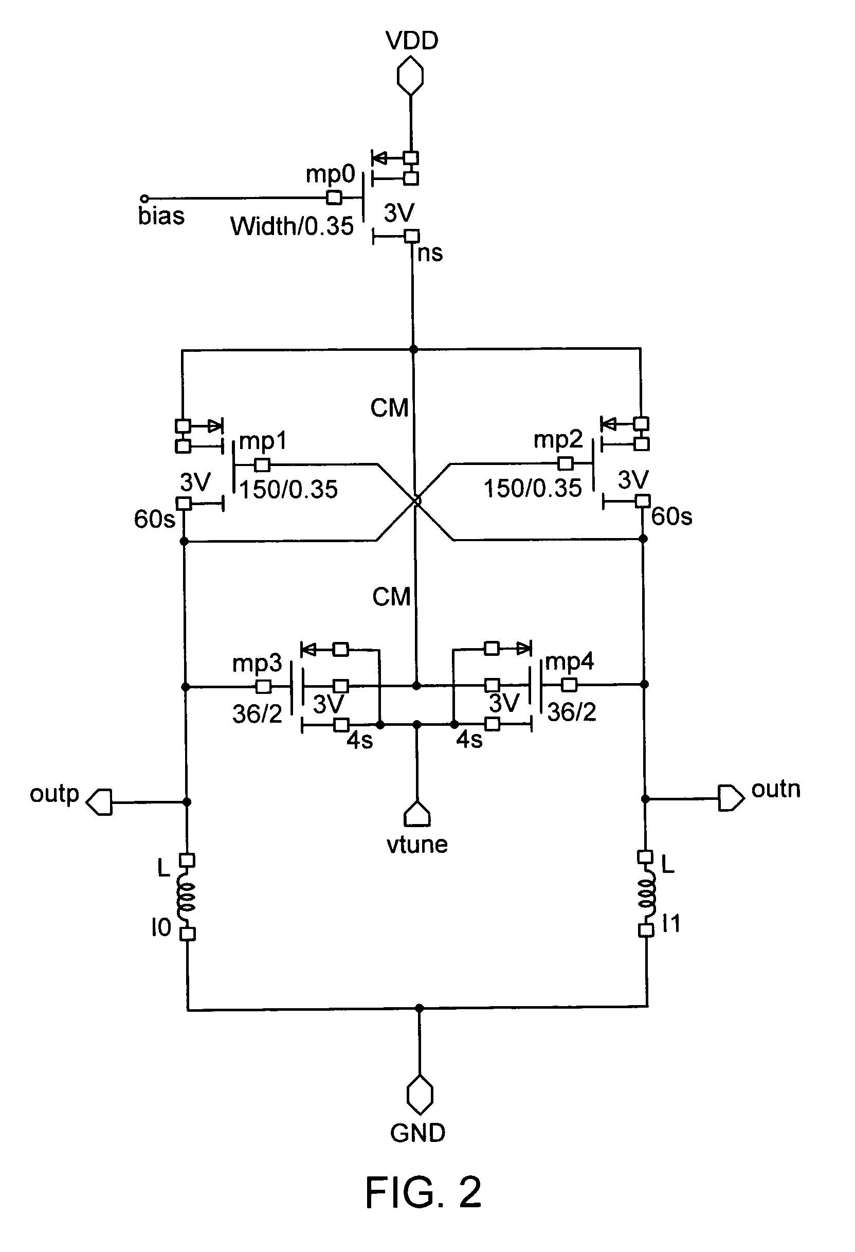
[0032]An improved MOS varactor for LC-tank VCO applications is formed by connecting the MOS varactor fourth terminal BG to a ground-isolated common mode point of the negative transconductance (Gm) devices used to pump the VCO tank, as shown in FIG. 1, which shows a VDD-referred tank, nMOS negative Gm device, cross-coupled differential VCO in a triple well CMOS process. This new varactor mode is referred to as the fourth mode (Mode 4). Since the tuning voltage and the common mode point are both VDD-referred, supply noise is not coupled into the tank by the varactor back gate capacitance and the VCO has excellent supply pushing (5 MHz / V simulated for this 10 GHz VCO example, or 90 ppm for a + / −5% 1.8V supply variation). For this example, the common mode point is held constant, at a Vgs from MN1, MN2 below VDD by the current source, MN0. (An automatic leveling control is used to adjust the current in the current source, MN0, to maintain a constant large signal tank swing across nMOS va...


PUM


Abstract

A metal oxide semiconductor (MOS) varactor device has a source and a drain connected to each other, and a back gate, electrically separate from the source and drain, which is connected to a circuit common mode point.

Description

FIELD OF THE INVENTION[0001]The invention generally relates to voltage controlled oscillators for radio frequency circuits, and specifically to an MOS varactor for such circuits.BACKGROUND ART[0002]Implementing monolithic voltage controlled oscillators (VCOs) in standard complementary metal oxide semiconductor (CMOS) technology is a major challenge for the design of radio-frequency (RF) CMOS transceiver integrated circuits (ICs). Recent work has shown that MOS devices for voltage control can produce better VCO performance than commonly used diode varactors. These advantages include better tuning range, better Q, and so better VCO phase noise. Both nMOS and pMOS variety devices can be used as varactors, typically with source and drain terminals shorted (S=D), and a tuning voltage applied to the gate terminal with respect to the source and drain.[0003]Several modes of MOS varactor operation are known depending on the connection of the fourth device terminal, the transistor back gate (...

Claims


Application Information

Patent Timeline
Patent Type & Authority Patents(United States)
IPC IPC(8): H03K3/01H01L27/08
CPCH01L27/0811H01L27/0808
Inventor TITUS, WARD S.KENNEY, JR., JOHN G.
Owner ANALOG DEVICES INC
Learn More