Gamma correction circuit

a correction circuit and gamma technology, applied in the field of gamma correction circuits, can solve the problems of severe quantization errors, approximation errors, etc., and achieve the effects of reducing the average quantization error, improving the smoothness of output signals, and reducing quantization errors

Inactive Publication Date: 2006-05-02
UNILOC 2017 LLC
View PDF13 Cites 9 Cited by
  • Summary
  • Abstract
  • Description
  • Claims
  • Application Information

AI Technical Summary

Benefits of technology

[0009]According to the invention, the lookup tables store discrete output intensity data and associated slope data for each of the input video signal intensities. The quantizer addresses the lookup tables by the most significant bits of the digitized input video signal intensity to read out the corresponding output intensity data and the associated slope data. The output intensity data are fed to the adder, the slope data are fed to the multiplier. The multiplier additionally receives the remaining bits of the input video signal intensity, multiplies the slope data with the remaining bits and couples the multiplication result to the adder. The adder performs an addition of the output intensity data and the multiplication result, this output being the corrected video signal, i.e. the gamma-corrected video signal, if the data stored in the two lookup tables correspond to the gamma correction characteristic. Whereas the circuit according to EP 0 457 522 multiplies the entire input video signal with the output from the second lookup table providing the slope data, the present invention multiplies only the least significant bits, i.e. the remainder of the input signal with the slope data. This reduces the hardware costs of the circuit without losing accuracy of the approximation.
[0011]In accordance with a preferred embodiment of the invention, the transfer function in the two lookup tables approximate a modified, i.e. a reduced gamma correction characteristic, and the output signal generated at the output of the adder passes additional processing circuitry which converts the signal into an approximation of a fully gamma-corrected video signal. By this embodiment, the quantization errors resulting from the quantization of the transfer function in the lookup tables are definitely reduced by programming a reduced non-linear curve in the lookup table, and processing the output of the adder further to a fully gamma-corrected video signal will proceed without increasing the quantization errors too much.
[0012]In a preferred embodiment of the invention, the requested gamma correction characteristic is defined as Y=Xgamma, X being the uncorrected video signal at the input of the circuit, Y being the corrected video signal at the output of the circuit, and gamma is the correction factor. In this embodiment, the lookup tables approximate a transfer function Y=Xgamma / 2, i.e. the non-linearity is reduced, and the quantization of such a flattened transfer function introduces reduced quantization errors. The output of the adder is then processed in the processing circuitry, i.e. in a squarer that squares the signal received from the adder. The squarer will double the value of gamma and output a fully gamma-corrected video signal, which is corrected by the factor gamma. If, for example, a gamma correction curve with gamma of 2.2 is to be realized, the lookup tables are programmed for a transfer function with gamma of 1.1, and the squarer will then double this value, so that the entire circuit realizes a gamma of 2.2 whereas the quantization errors correspond to a gamma of 1.1 and are thus remarkably reduced. In accordance with the invention, this additional processing is applied for gamma values larger than approximately 1.4.
[0017]If, however, only a r bit wide output path to the display is present, the additional (q+p−r) bits of resolution are preserved and separated in an error propagation unit which adds these extra (q+p−r) bits, i.e. the least significant bits of each signal representing a pixel, to the right neighboring, i.e. following up pixel. This transfer of discarded bits from one pixel to the following up pixel reduces the visibility of the quantization errors, keeping the low frequency component of the quantization noise small.
[0018]This embodiment of the invention is a form of noise shaping, the feedback of the least significant bits by error propagation suppresses the low frequency part of the spectrum of the quantization noise. Perceptually this is the more important part, so the quantization will be less visible. Even if the output video path is only r bits wide, r≦(q+p), the gamma correction circuit perceptually preserves a much better quality. If for example the output path has a width of 5 to 10 bits, the output quality can be preserved much higher, for example up to 14 bits. This allows the use of cheaper interlinks or cheaper D / A converters, i.e. 8 bit converters and still claim 10 or more bits of precision. Noise shaping by itself is not a new invention. We use it here to preserve most of the extra precision that is created by the linear interpolation of the gamma lookup table and / or by the extra processing circuitry (the squarer).
[0020]Hence, according to the invention, the gamma correction circuit particularly improves the smoothness of the output signal, and the optional processing circuitry reduces the quantization error significantly near the black, when a large value of gamma is desired, which is typically for linear-light displays. The optional error propagation reduces the average quantization error even more, which allows the use of cheaper interlinks or cheaper D / A converters at the output, at the cost of creating only some high frequency quantization noise.

Problems solved by technology

In the near black region, the approximation then suffers from severe quantization errors.

Method used


Image

  • Gamma correction circuit
  • Gamma correction circuit
  • Gamma correction circuit

Examples


Embodiment Construction

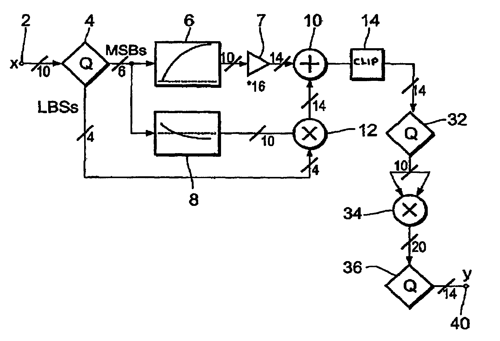
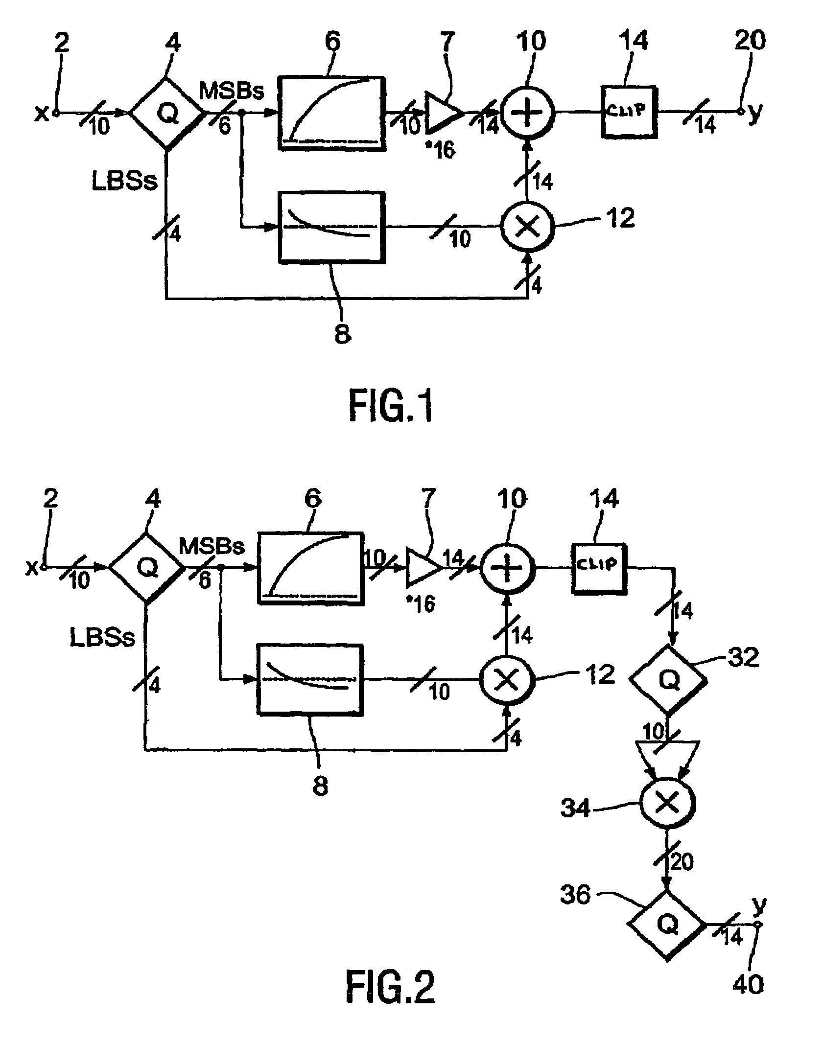
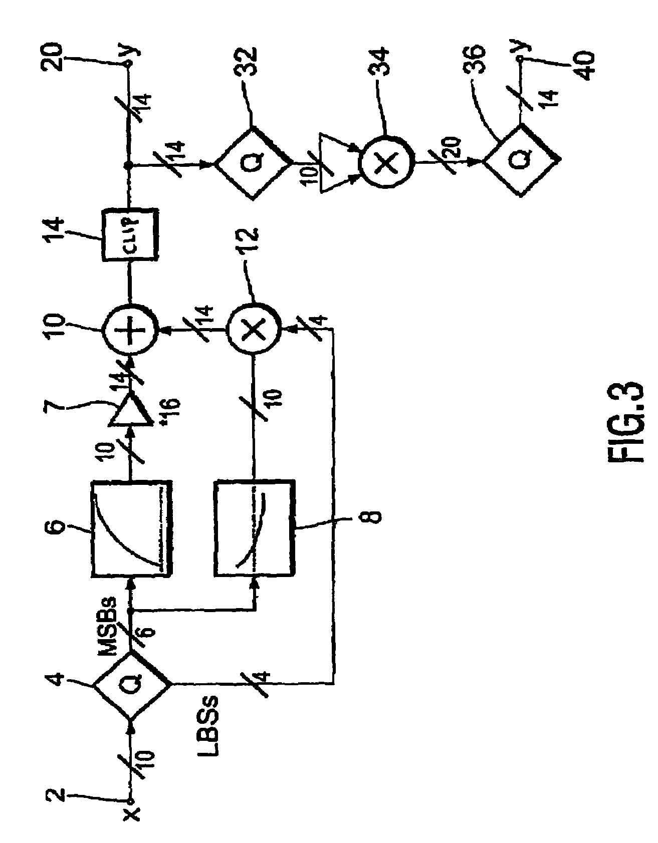
[0026]FIGS. 1, 2 and 3 show three different embodiments of a gamma correction circuit according to the invention, all three embodiments include however, the same basis design. The circuit includes a first lookup table 6 for storing discrete output intensity data of a non-linear transfer function, and it includes a second lookup table 8 for storing the slope data of the non-linear transfer function, associated to the respective output intensity data stored in the first lookup table. The respective output intensity data and the associated slope data are stored in the first and second lookup table 6, 8 under the same address, this address being defined by the corresponding input video signal intensities of the input signal.

[0027]The output of the first lookup table is connected via shifting unit 7, the operation of which will be described later, to the first input of an adder 10. The output of the second lookup table 8 is connected to a first input of a multiplier 12, the output of whi...


PUM


Abstract

A gamma correction circuit for correcting a digital video signal, the circuit comprising first (6) and second (8) lookup tables for storing discrete output intensity data and the associated slope data of a non-linear transfer function, respectively, for each of the discrete input video signal intensities, an adder (10) having a first input connected to the output of the first lookup table, a multiplier (12) having a first input connected to the output of the second look-up table (8), characterized by a quantizer (4) for providing the most significant bits of the incoming video signal to address the first (6) and second (8) lookup tables and to transfer the corresponding output intensity data to the adder (10) and the associated slope data to the multiplier (12), the quantizer (4) transmitting the remaining least significant bits of the input video signal to the second input of the multiplier (12), the multiplier (12) multiplying the slope data with the remaining least significant bits and feeding the multiplication result to the second input of the adder (10), the adder (10) adding the output intensity data and the multiplication result to generate a corrected video signal.

Description

FIELD OF THE INVENTION[0001]The invention relates to a gamma correction circuit for correcting a digital video signal.BACKGROUND OF THE INVENTION[0002]Gamma correction is well known in the art to correct video intensity values for causing a linear range of video intensity values to be displayed on various displays. The video data obtained by photoelectric transfer and having a non-linear characteristic are corrected in accordance with a pre-given correction curve, the so-called gamma correction characteristic, so that the image is displayed as a linear gradation of intensities.[0003]As typical video displays, for example cathode ray tubes (CRTs), have a non-linear transfer characteristics, i.e. the reproduced brightness on the CRT screen is a non-linear “gamma” function of the controlled-grid video drive (e.g. gamma=2.2). To achieve a linear gradation of intensities, the video signal at the TV transmitter side is pre-corrected (e.g. gamma=0.45) for a standard CRT display. When displ...

Claims


Application Information

Patent Timeline
Patent Type & Authority Patents(United States)
IPC IPC(8): H04N5/202G09G3/36G09G3/20G09G5/00
CPCH04N5/202
Inventor STESSEN, JEROEN HUBERT CHRISTOFFEL JACOBUSMACCATO, ANDREAOSLICK, MITCHELL
Owner UNILOC 2017 LLC
Why Eureka
Try Eureka