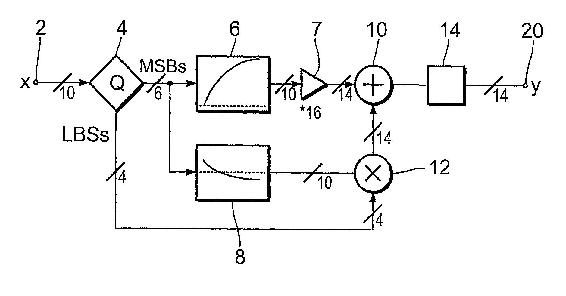
[0009] According to the invention, the lookup tables store discrete output intensity data and associated slope data for each of the input video signal intensities. The quantizer addresses the lookup tables by the most significant bits of the digitized input video
signal intensity to read out the corresponding output intensity data and the associated slope data. The output intensity data are fed to the adder, the slope data are fed to the multiplier. The multiplier additionally receives the remaining bits of the input video
signal intensity, multiplies the slope data with the remaining bits and couples the multiplication result to the adder. The adder performs an addition of the output intensity data and the multiplication result, this output being the corrected video signal, i.e. the gamma-corrected video signal, if the data stored in the two lookup tables correspond to the gamma correction characteristic. Whereas the circuit according to EP 0 457 522 multiplies the entire input video signal with the output from the second
lookup table providing the slope data, the present invention multiplies only the least significant bits, i.e. the remainder of the input signal with the slope data. This reduces the hardware costs of the circuit without losing accuracy of the approximation.
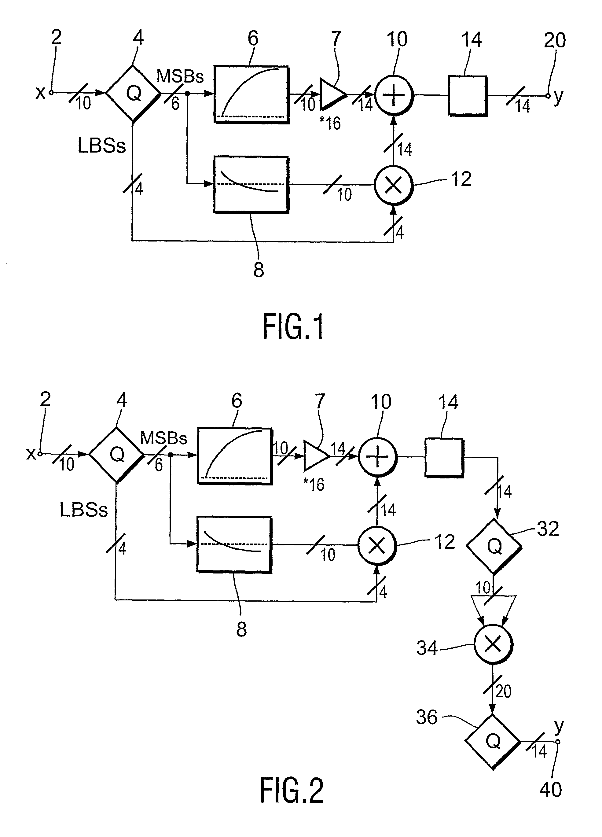
[0011] In accordance with a preferred embodiment of the invention, the
transfer function in the two lookup tables approximate a modified, i.e. a reduced gamma correction characteristic, and the output signal generated at the output of the adder passes additional
processing circuitry which converts the signal into an approximation of a fully gamma-corrected video signal. By this embodiment, the quantization errors resulting from the quantization of the
transfer function in the lookup tables are definitely reduced by
programming a reduced non-linear curve in the
lookup table, and
processing the output of the adder further to a fully gamma-corrected video signal will proceed without increasing the quantization errors too much.
[0012] In a preferred embodiment of the invention, the requested gamma correction characteristic is defined as Y=X.sup.gamma, X being the uncorrected video signal at the input of the circuit, Y being the corrected video signal at the output of the circuit, and gamma is the correction factor. In this embodiment, the lookup tables approximate a transfer function Y=X.sup.gamma / 2, i.e. the non-
linearity is reduced, and the quantization of such a flattened transfer function introduces reduced quantization errors. The output of the adder is then processed in the
processing circuitry, i.e. in a squarer that squares the signal received from the adder. The squarer will double the value of gamma and output a fully gamma-corrected video signal, which is corrected by the factor gamma. If, for example, a gamma correction curve with gamma of 2.2 is to be realized, the lookup tables are programmed for a transfer function with gamma of 1.1, and the squarer will then double this value, so that the entire circuit realizes a gamma of 2.2 whereas the quantization errors correspond to a gamma of 1.1 and are thus remarkably reduced. In accordance with the invention, this additional processing is applied for gamma values larger than approximately 1.4.
[0017] If, however, only a r bit wide output path to the display is present, the additional (q+p-r) bits of resolution are preserved and separated in an error propagation unit which adds these extra (q+p-r) bits, i.e. the least significant bits of each signal representing a pixel, to the right neighboring, i.e. following up pixel. This transfer of discarded bits from one pixel to the following up pixel reduces the
visibility of the quantization errors, keeping the
low frequency component of the quantization
noise small.
[0018] This embodiment of the invention is a form of
noise shaping, the feedback of the least significant bits by error propagation suppresses the
low frequency part of the spectrum of the quantization
noise. Perceptually this is the more important part, so the quantization will be less visible. Even if the output video path is only r bits wide, r.ltoreq.(q+p), the gamma correction circuit perceptually preserves a much better quality. If for example the output path has a width of 5 to 10 bits, the output quality can be preserved much higher, for example up to 14 bits. This allows the use of cheaper interlinks or cheaper D / A
converters, i.e. 8 bit
converters and still claim 10 or more bits of precision.
Noise shaping by itself is not a new invention. We use it here to preserve most of the extra precision that is created by the linear interpolation of the gamma lookup table and / or by the extra processing circuitry (the squarer).
[0020] Hence, according to the invention, the gamma correction circuit particularly improves the smoothness of the output signal, and the optional processing circuitry reduces the quantization error significantly near the black, when a large value of gamma is desired, which is typically for linear-light displays. The optional error propagation reduces the average quantization error even more, which allows the use of cheaper interlinks or cheaper D / A
converters at the output, at the cost of creating only some
high frequency quantization noise.

