System verification equipment, system verification method and LSI manufacturing method using the system verification equipment

Inactive Publication Date: 2006-05-02
RENESAS TECH CORP
View PDF14 Cites 14 Cited by
  • Summary
  • Abstract
  • Description
  • Claims
  • Application Information

AI Technical Summary

Benefits of technology

[0036]The above system verification equipment to be operated by an intellectual property provider preferably encrypts vector data before transmitting it across the

Problems solved by technology

However, because the systems to be designed becomes larger each year, a verification process for ensuring the system operates properly becomes complex.
If design data is used, the design data can be verified, but it takes rather long processing time to execute the simulation sequentially due to the detailed descriptions of the design data.
However, the design data of a third party module cannot be 100% verified with a verification model because of its abstract or simplified nature.
However, the use of the verification model presents the following problems.
First, secret information leaks out by disclosing the verification model.
Secondly, the verification model is subject to modification or alteration during specification change or debugging.
Thirdly, it is difficult to quantitatively review how the verification model has actually been used.
Fourthly, a fixed charge is set for use of the verification model, according to the currently applied charging method, and it is expensive.
In the above manner in which the medium having all data of the verification model is delivered, there is a risk of leaking out of the technique for generating the verification model.
In addition, module specification change may cause discrepancy between the existing verification model and the actual module operation.
With respect to the fourth problem, the current charge for the verification model includes the price of the storage medium with the verification model data and the charge for maintenance service rendered to its users.
However, the users must pay a fixed rate whether the user will use the verification model repeatedly or only once and the charge is generally high.
In consequence, this would be a problem particularly for those users who want to apply the verification model to a small system to introduce a test module, which use lacks any economy of scale.

Method used


Image

  • System verification equipment, system verification method and LSI manufacturing method using the system verification equipment
  • System verification equipment, system verification method and LSI manufacturing method using the system verification equipment
  • System verification equipment, system verification method and LSI manufacturing method using the system verification equipment

Examples


embodiment 1

(1) Embodiment 1

[0054]A preferred Embodiment 1 of the system verification equipment of the present invention is described with reference to FIGS. 1 and 2.

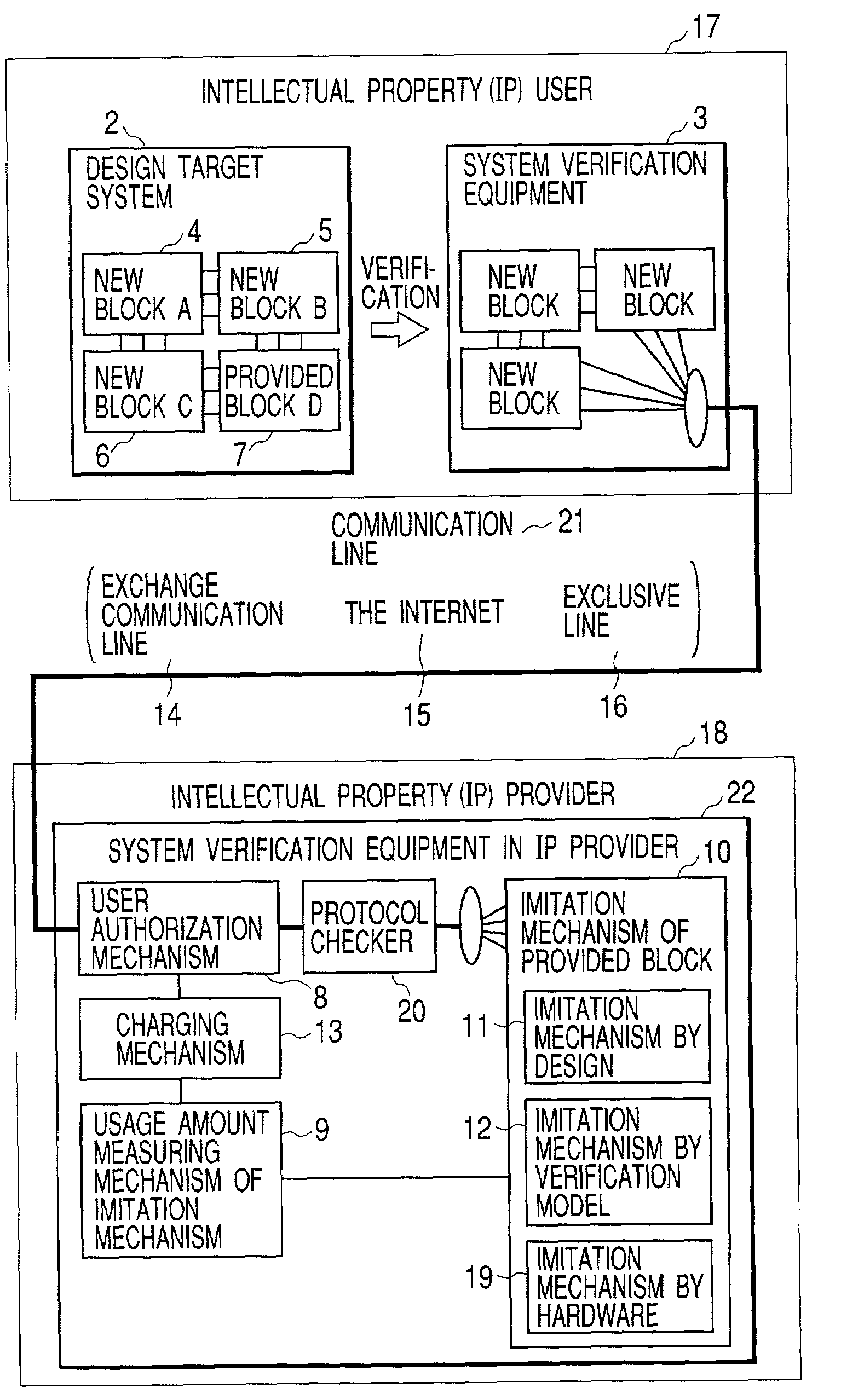
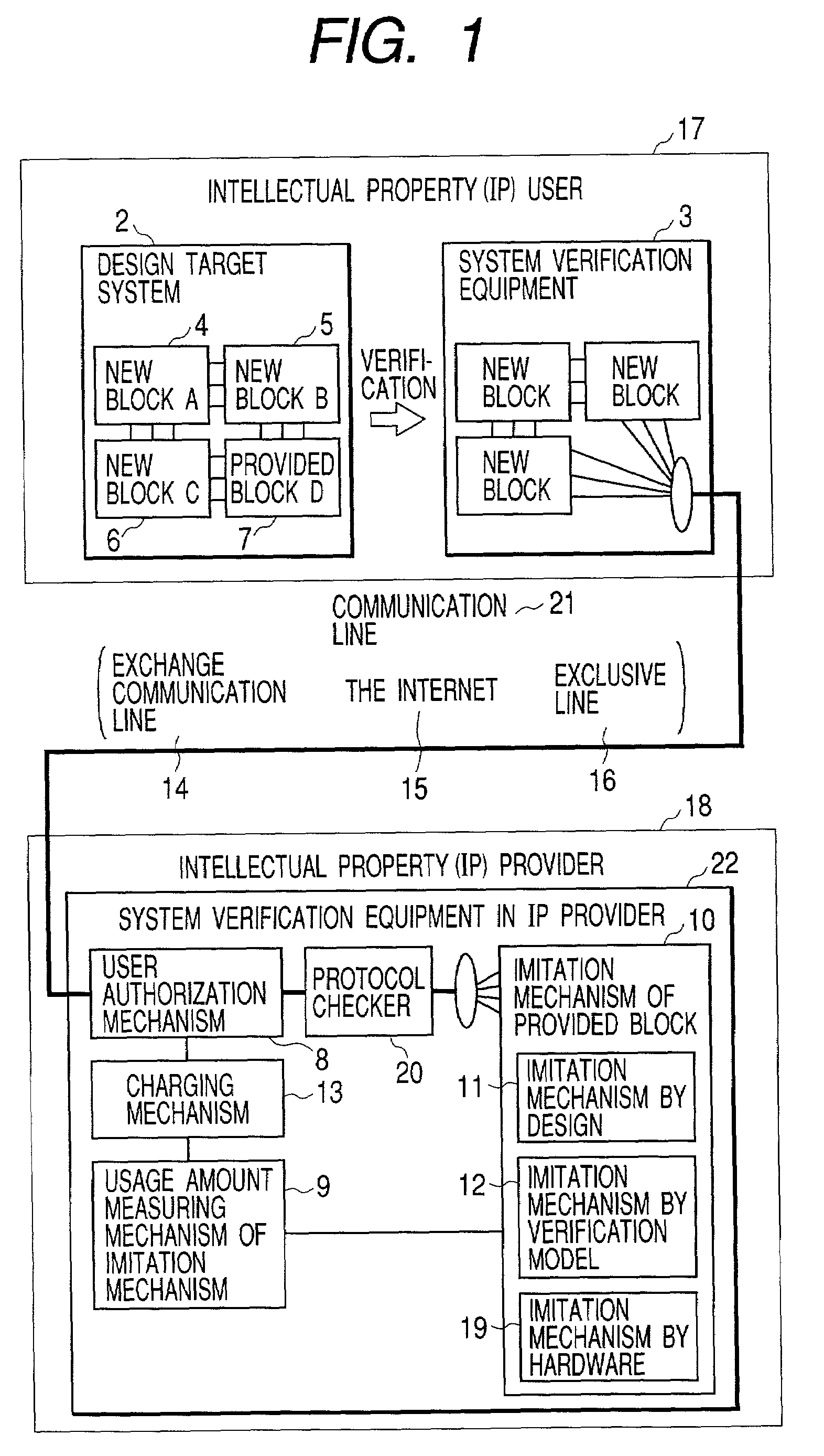
[0055]FIG. 1 shows a conceptual diagram of the present invention, and FIG. 2 shows its illustrative structural diagram. A system verification equipment 3 to be operated by an intellectual property (IP) user is presented on the upper side of FIGS. 1 and 2. In FIGS. 1 and 2, another system verification equipment 22 to be operated by an intellectual property (IP) provider is presented on the lower side. The following explanation of Embodiment 1 focuses on the system verification equipment 3 to be operated by an intellectual property (IP) user. The system verification equipment 22 to be operated by an intellectual property (IP) provider will be explained in detail later in Embodiment 2.

[0056]To explain Embodiment 1, an illustrative example is used provided where a system designer creates three new blocks (A4, B5, and C6) and receives b...

embodiment 2

(2) Embodiment 2

[0089]Another preferred embodiment (Embodiment 2) of the system verification equipment of the present invention is described with reference to FIGS. 1 and 2.

[0090]In embodiment 2, it is assumed that a system designer who builds a system with intellectual property provided by an outside entity with newly created blocks. The environment for verifying such a system is explained as follows. The system designer verifies the blocks designed using the mentioned system verification equipment 3 and the equipment possessed by the entity. For blocks protected as intellectual property from outside, the designer does not verify them in-house. Instead, a provided block is verified by sending an input vector sequence to the intellectual property provider's verification equipment and receiving an output vector sequence over a communication line. This manner is practical because the provided blocks protected as intellectual property have been verified for their internal logic, and it...

embodiment 3

(3) Embodiment 3

[0114]A further preferred embodiment (Embodiment 3) of the system verification equipment of the present invention is described as follows.

[0115]FIG. 9 represents an overview of a process for designing an LSI. In the phase of specification investigation 150, the specifications of the LSI are determined. Then, a design 151 is generated according to the specifications. After it is verified that the LSI design has properly been finished according to the specifications in the verification phase 152, the fabrication 153 of the LSI is carried out.

[0116]If the LSI specifications include a block or blocks protected as intellectual property by an outside entity as determined by the specification investigation, it is advisable to use the system verification equipment described in Embodiment 1 or 2 in the process of verification 152.

[0117]If an LSI system design is developed, part of which is made by using intellectual property provided from outside, the present invention is app...


PUM


Abstract

A system designed, including commercially distributed modules protected as intellectual property (IP), is verified in a manner that the IP provider and the user communicate with each other over a communication line to complete the system design verification. A system verification equipment to be operated by the IP provider receives from the system designer across the communication line an input vector at time n to a module provided to the system designer who designed the system integrated using one or more provided IP modules. After simulating the module operation with the input vector, the verification equipment returns an output vector obtained at time n+1 to the system designer over the communication line. The verification equipment examines the input vectors to the provided IP modules and records statistics information thereof, based on which the provider will quantitatively understand how the provided modules have been used. Such information is used by the provider to determine the specifications of modules to be provided next time and to market modules meeting user needs. The verification equipment determines the service charge for each IP user by the quantity of load worked on its verification system to fulfill the service, according to the quantity of input vector data transmitted to the equipment by the user. Furthermore, the verification equipment encrypts vector data before transmitting it across the communication line and decrypts vector data after receiving it over the line such that the data is prevented from intercepted by a third party.

Description

FIELD OF THE INVENTION[0001]The present invention relates to equipment and a method for verifying an integrated system design, including in-house designed modules and at least one module protected as intellectual property (IP) and an LSI manufacturing method using such equipment. More particularly, the present invention relates to a couple of system verification equipment, one provided as the system designer's verification system and the other as the IP provider's verification system, both of which are interconnected by a communication line through which the former system requests the latter system to verify the provided module, and a system verification method using such equipment and an LSI manufacturing method using such equipment.BACKGROUND OF THE INVENTION[0002]In the field of system design, lately, the reuse of past design modules becomes popular to enhance the design efficiency. The system scale is diverse, ranging from a system LSI which is a system comprised of a plurality ...

Claims


Application Information

Patent Timeline
IPC IPC(8): G06F17/50H01L21/82H01L21/822H01L27/04
CPCG06F17/5022G06F2217/66G06F30/33G06F2115/08
Inventor AKITA, YOHEI
Owner RENESAS TECH CORP
Why Eureka
Try Eureka