Clamping fixture

Active Publication Date: 2006-05-09
LIOU FERNG JONG
View PDF6 Cites 22 Cited by
  • Summary
  • Abstract
  • Description
  • Claims
  • Application Information

AI Technical Summary

Benefits of technology

[0008]A primary object of the present invention is to provide a clamping fixture, in which a handle for locking a movable jaw in place is located above the gauge rod and

Problems solved by technology

1. Since the trigger A is located at a lower portion of the clamping fixture, it must be pulled rearward using a finger to push the shift plate E into an inclined position.
2. A user has to exert efforts to hold the

Method used


Image

  • Clamping fixture
  • Clamping fixture
  • Clamping fixture

Examples


Example

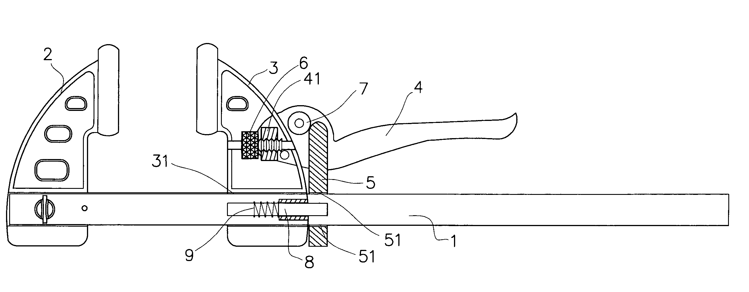
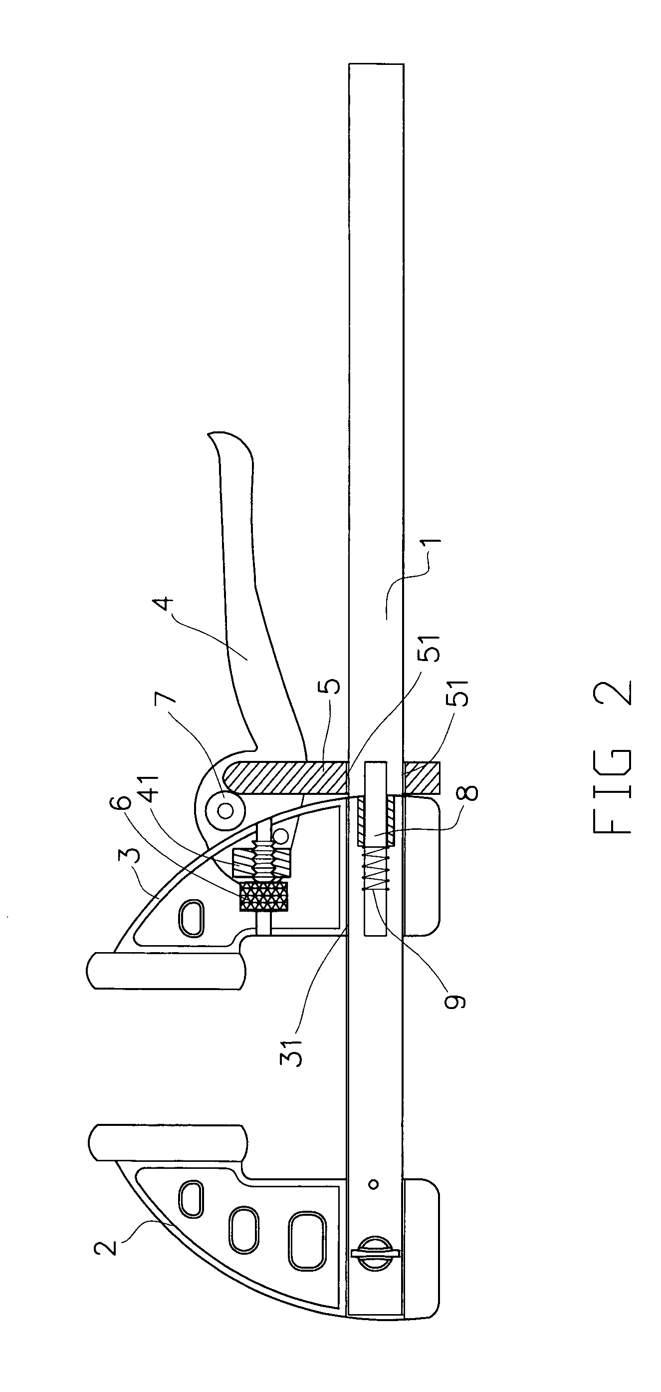
[0017]Please refer to FIGS. 2 and 3 that are two partially sectioned side views of a clamping fixture according to the present invention. As shown, the clamping fixture includes a gauge rod 1, a fixed jaw 2, a movable jaw 3, a handle 4, and a shift plate 5.

[0018]The fixed jaw 2 is locked to an end of the gauge rod 1. The movable jaw 3 is provided at a lower portion with a horizontal groove 31, with which the gauge rod 1 is engaged to allow the movable jaw 3 to linearly reciprocate along the gauge rod 1.

[0019]The handle 4 works as a lever, and has a nut 41 connected to one side of a front end thereof using a shaft 42. The nut 41 is mounted on a screw rod having a turning knob 6. Two ends of the screw rod are separately fixedly connected to front and rear frames of the movable jaw 3. When the turning knob 6 is turned, the nut 41 is brought to move forward or backward along the screw rod, and the handle 4 is moved along with the nut 41. In this manner, the handle 4 can be finely adjust...


PUM


Abstract

A clamping fixture includes a gauge rod having a fixed and a movable jaw mounted thereon, a lever-like handle, and a shift plate having a lower slot, via which the gauge rod is extended. The shift plate is connected to a rear side of the movable jaw via two shafts having compression springs mounted thereon. When the handle is downward pulled, a roller on the handle pushes the shift plate to turn clockwise, bringing the slot into an inclined position to firmly press against the gauge rod and thereby becomes immovable to stop the movable jaw from moving. The handle has a nut engaged with a screw rod mounted on the movable jaw. When the screw rod is turned, the nut and accordingly the handle are axially finely adjusted until a workpiece is firmly clamped between the two jaws.

Description

FIELD OF THE INVENTION[0001]The present invention relates to a clamping fixture, and more particularly to a clamping fixture provided with a lever-like handle for conveniently locking a shift plate in place and preventing a movable jaw of the fixture from moving along a gauge rod, so as to firmly clamp a workpiece between the movable jaw and a fixed jaw.BACKGROUND OF THE INVENTION[0002]FIG. 1 shows a conventional clamping fixture, in which a movable jaw C fixedly mounted to an end of a gauge rod D is held in place via a trigger A located at a lower portion of the clamping fixture. When the trigger A is pulled, a shift plate E located immediately behind the trigger A is brought into an inclined position, such that a through slot B provided on the shift plate E also becomes inclined to tightly press against and there by push and move the gauge rod D that extends through the slot B, so that the movable jaw C fixedly mounted on the gauge rod D is moved to a desired position.[0003]The ab...

Claims


Application Information

Patent Timeline
IPC IPC(8): B25B1/00
CPCB25B5/068
Inventor LIOU, FERNG-JONG
Owner LIOU FERNG JONG
Why Eureka
Try Eureka