Rotatable variable resistor with clicking mechanism
a rotating variable and resistor technology, applied in the direction of resistor details, adjustable resistors, resistors with sliding contact, etc., can solve the problems of affecting the operation of the resistor, and the number of components, so as to reduce the noise or eliminate the effect of noise without deteriorating the operational feel
- Summary
- Abstract
- Description
- Claims
- Application Information
AI Technical Summary
Benefits of technology
Problems solved by technology
Method used
Image
Examples
first preferred embodiment
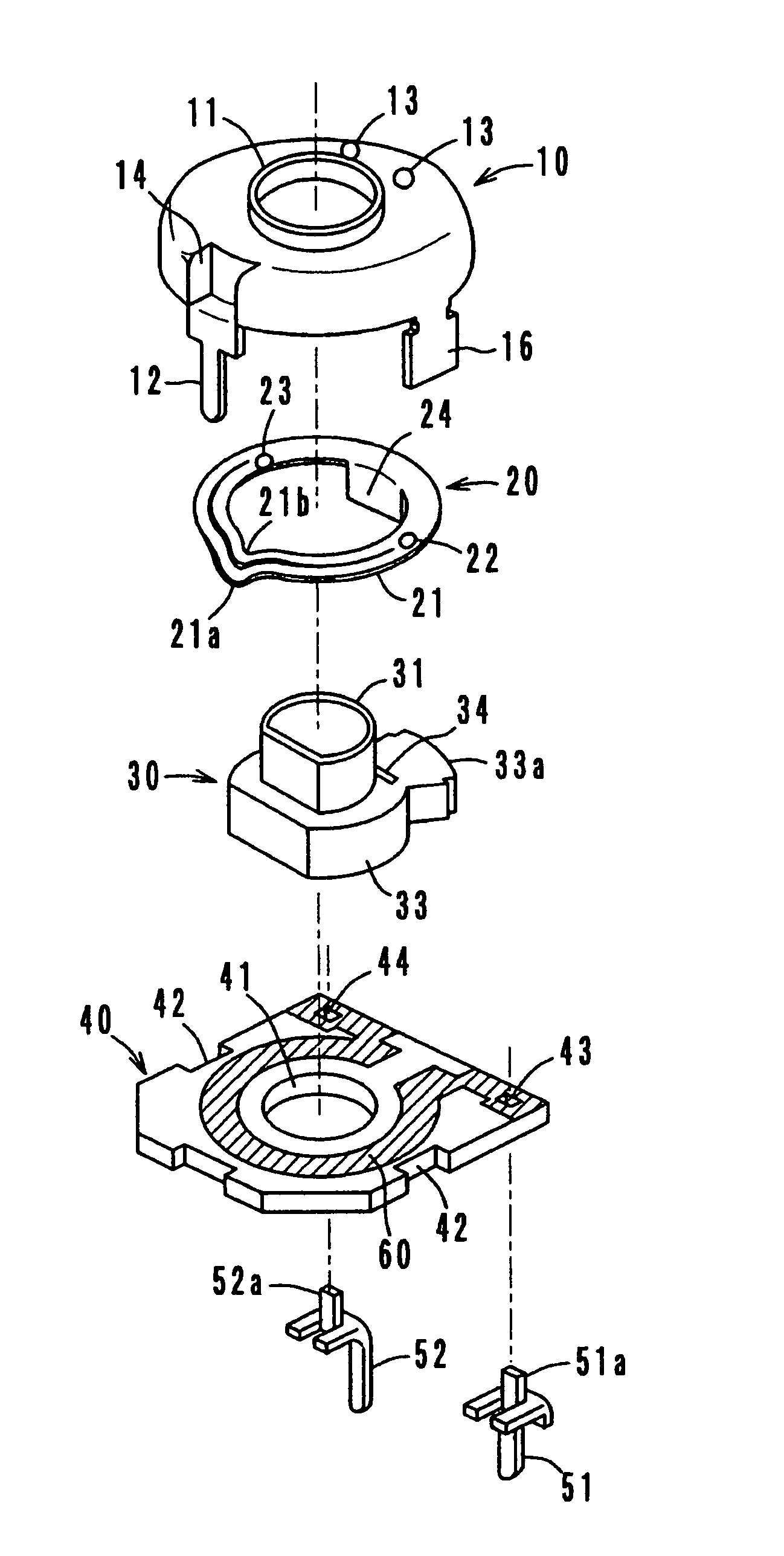
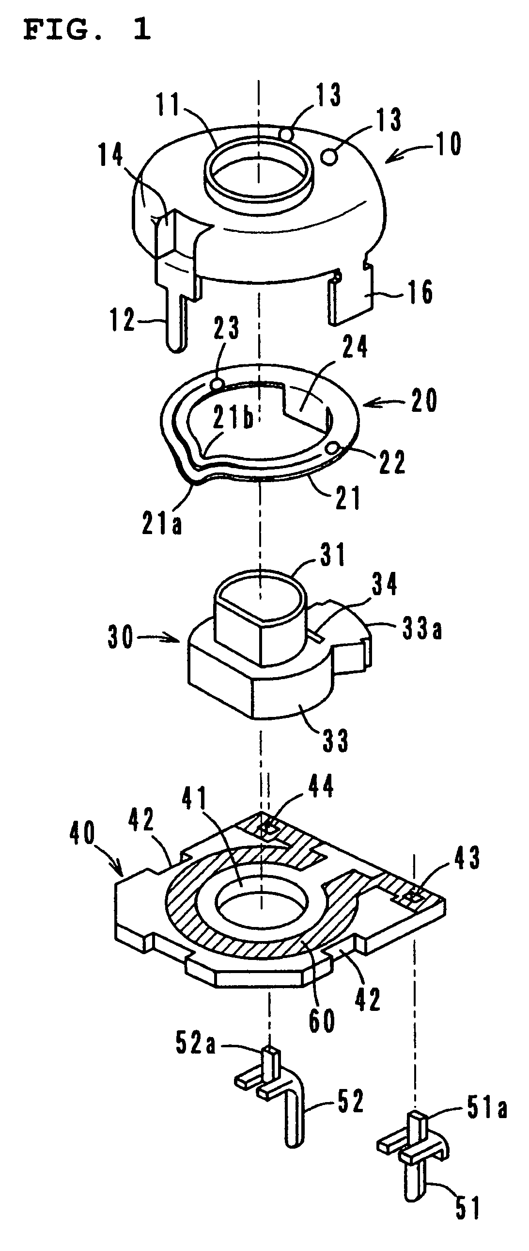
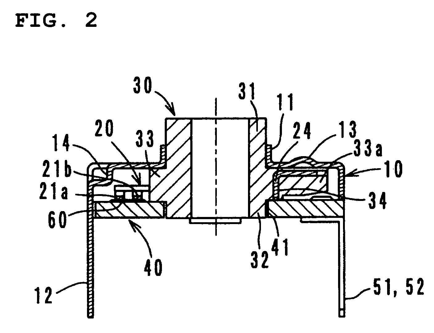
[0043]A first preferred embodiment will be described with reference to FIGS. 1 to 6.
[0044]Referring to FIGS. 1 to 4, the rotatable variable resistor provided with a clicking mechanism according to the first preferred embodiment of the present invention preferably includes a cover 10, a wiper 20, a rotor 30, a resistor substrate 40, and external terminals 51 and 52. The wiper 20 and the rotor 30 define a rotary unit. The cover 10, the resistor substrate 40, and the external terminals 51 and 52 define a fixed unit.
[0045]The cover 10 is preferably formed of a conductive material and has an integrated structure which includes a substantially cylindrical portion 11 in the approximate central upper surface of the cover 10, an external terminal 12 extending downward along the side of the cover 10, and a pair of tabs 16 extending downward along the side of the cover 10. Moreover, the cover 10 is provided with a pair of semispherical clicking-depressions 13.
[0046]The wiper 20 is preferably f...
second preferred embodiment
[0058]A second preferred embodiment will now be described with reference to FIG. 7.
[0059]FIG. 7 illustrates a relevant section, i.e. a section of the wiper 20, of the rotatable variable resistor provided with a clicking mechanism according to the second preferred embodiment of the present invention. The variable resistor of the second preferred embodiment basically includes the same components as those included in the variable resistor of the first preferred embodiment. The difference is that the non-clicking projection 23 of the wiper 20 in the second preferred embodiment alternatively has a top portion 23a which extends linearly in the rotational direction of the wiper 20.
[0060]In detail, a protruding tab is provided at one side of the arm segment 21, and the tab is bent upward so as to form the non-clicking projection 23. Since the top portion 23a is longer in the sliding direction, the abrasion resistance of the top portion 23a is improved. This contributes to a longer life cycl...
third preferred embodiment
[0061]A third preferred embodiment will now be described with reference to FIG. 8.
[0062]FIG. 8 illustrates a relevant section, i.e. a section of the wiper 20, of the rotatable variable resistor provided with a clicking mechanism according to the third preferred embodiment of the present invention. The variable resistor of the third preferred embodiment basically includes the same components as those included in the variable resistor of the first preferred embodiment.
[0063]The difference is that the non-clicking projection 23 in the third preferred embodiment has a flat top portion whose width in a direction is greater than that of each clicking depression 13, and the surface of the flat top portion contacts the undersurface of the cover 10. Referring to FIG. 9B, the sliding track T1 of the top of the clicking projection 22 is located within the sliding track T2 of the non-clicking projection 23 in the radius direction.
[0064]In detail, the non-clicking projection 23 is formed by bend...
PUM
 Abstract
Description
Claims
Application Information
 - R&D
- Intellectual Property
- Life Sciences
- Materials
- Tech Scout
- Unparalleled Data Quality
- Higher Quality Content
- 60% Fewer Hallucinations
Browse by: Latest US Patents, China's latest patents, Technical Efficacy Thesaurus, Application Domain, Technology Topic, Popular Technical Reports.
© 2025 PatSnap. All rights reserved.Legal|Privacy policy|Modern Slavery Act Transparency Statement|Sitemap|About US| Contact US: help@patsnap.com


