Methods for generating an adaptively sampled distance field of an object with specialized cells

a distance field and object technology, applied in the field of computer graphics, can solve the problems of hardware support, major bottleneck in the hinting process, and difficulty in interpreting hinting rules,

Active Publication Date: 2006-05-09
MITSUBISHI ELECTRIC RES LAB INC
View PDF14 Cites 49 Cited by
  • Summary
  • Abstract
  • Description
  • Claims
  • Application Information

AI Technical Summary

Problems solved by technology

While there have been attempts to design automated and semi-automated hinting systems, the hinting process remains a major bottleneck in the design of new fonts and in the tuning of existing fonts for low-resolution display devices.
In addition, the complexity of interpreting hinting rules precludes the use of hardware for font rendering.
The lack of hardware support forces compromises to be made during software rasterization, such as the use of fewer samples per pixel and poor filtering methods, particularly when animating type in real time.
However, even that approach is often too slow for real-time rendering, as required for animated type, and the rendered glyphs suffer from spatial and temporal aliasing.
Unfortunately, traditional outline-based fonts and corresponding methods have limitations in all of these areas.
Font hinting is labor intensive and expensive.
For example, developing a well-hinted typeface for Japanese or Chinese fonts, which can have more than ten thousand glyphs, can take years.
Because the focus of hinting is on improving the rendering quality of body type, the hints tend to be ineffective for type placed along arbitrary paths and for animated type.
Although high quality filtering can be used to antialias grayscale type in static documents that have a limited number of font sizes and typefaces, the use of filtering in animated type is typically limited by real-time rendering requirements.
First, they require many samples per pixel component to get adequate quality, which is inefficient.
When rendering on alternative pixel layouts comprising many components, e.g., such as the layouts described in U.S. patent application publication number 20030085906, their methods become impractical.
Second, they exploit the vertical or horizontal striping of a display to enable reuse of samples for neighboring pixel components, which fails to work with many alternative pixel component layouts.
Third, they use a poor filter when sampling each component because of the inefficiencies of their methods when using a better filter.
Fourth, the methods taught do not provide any measure for mitigating color fringing on alternative pixel component layouts.
Re-rendering usually requires re-interpreting hints, which is inefficient.
Redoing hints is both expensive and time consuming.
Those prior art methods can be problematic for a number of reasons.
For example, the Painter's Algorithm results in color artifacts between closely spaced glyphs when rendering on liquid crystal displays (LCDs), organic light emitting diodes (OLEDs), or similar display technologies with separately addressable pixel components.
Prior art methods that blend pixel colors or intensities require additional computation and storage for alpha values and exhibit various artifacts such as edge blurring or edge dropout depending on the blending method used.
In addition, coverage values determined for a set of overlapping objects using prior art coverage-based antialiasing cannot, in general, be blended together to represent the actual coverage of the combined object.
All of those prior art methods that combine prior to rendering require additional storage space and complex operations to generate the composite object.
Both approaches have problems as described above.

Method used


Image

  • Methods for generating an adaptively sampled distance field of an object with specialized cells
  • Methods for generating an adaptively sampled distance field of an object with specialized cells
  • Methods for generating an adaptively sampled distance field of an object with specialized cells

Examples


Embodiment Construction

[0075]Distance Field Representation of Glyphs

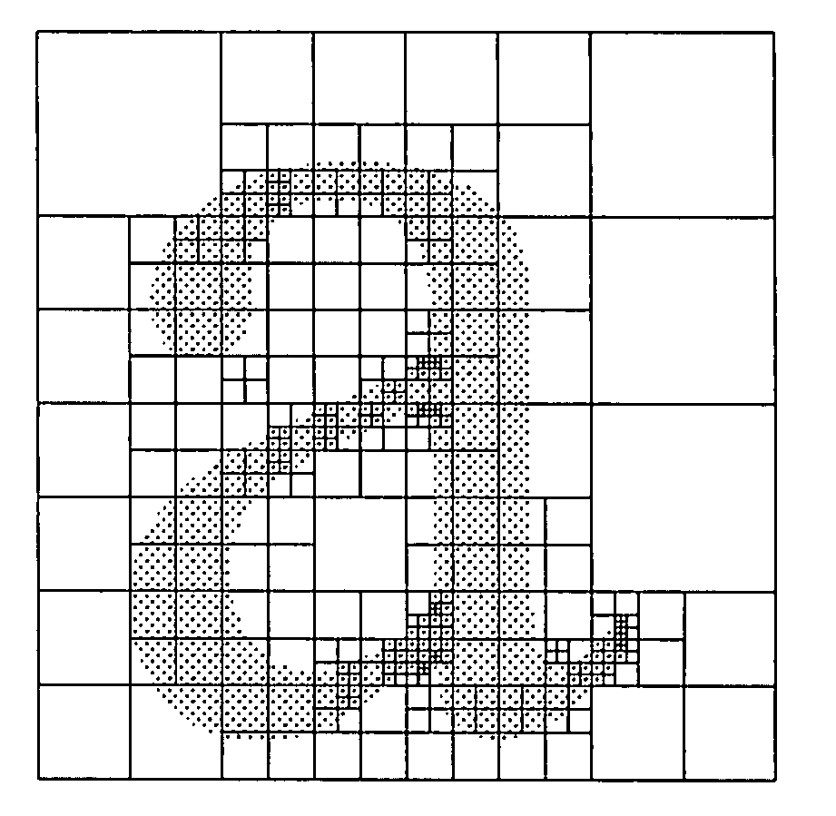
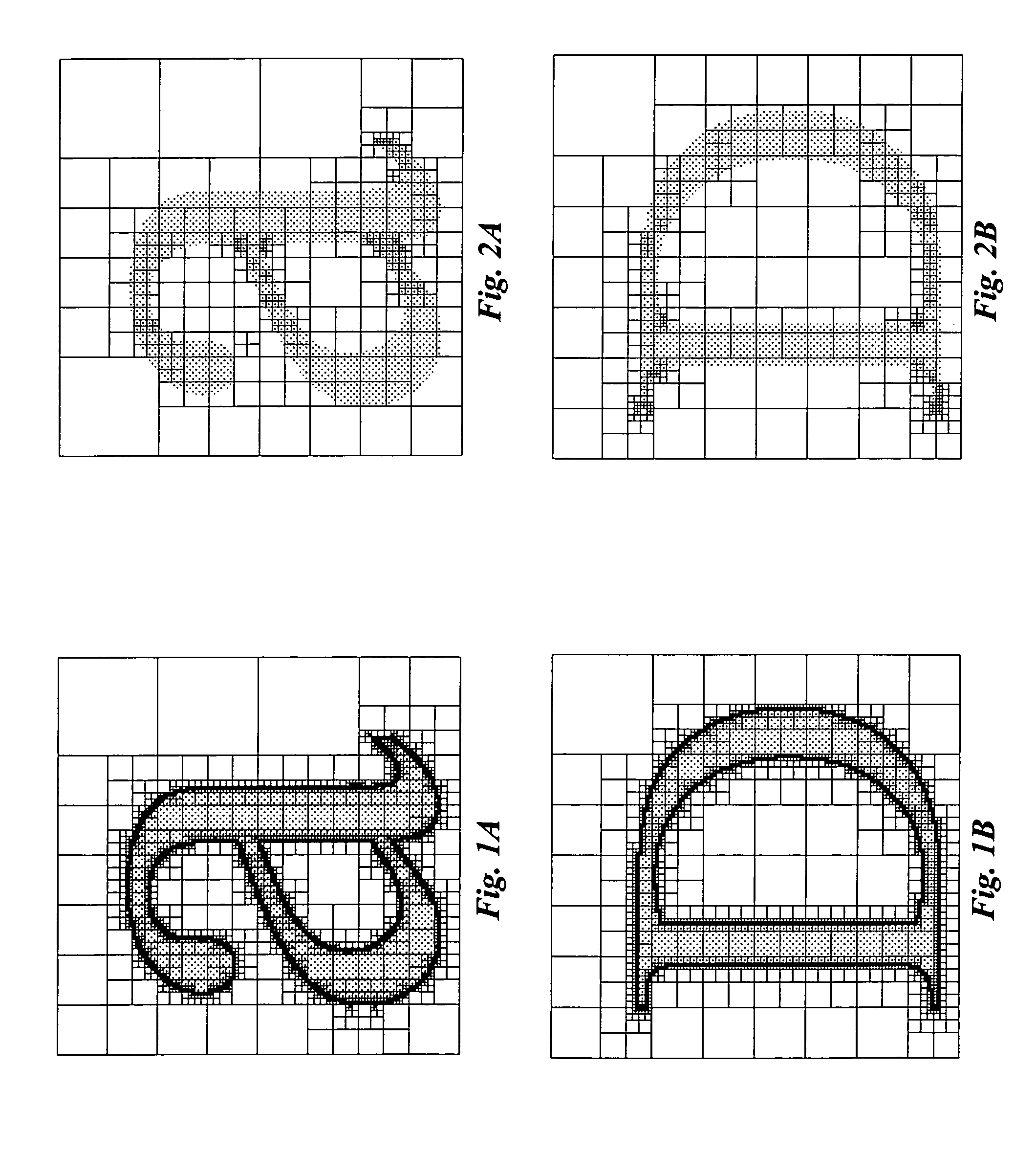
[0076]Our invention represents a closed two-dimensional shape S, such as a glyph, a corporate logo, or any digitized representation of an object, as a two-dimensional signed distance field D. For the purpose of our description, we use glyphs.

[0077]Informally, the distance field of a glyph measures a distance, e.g., a minimum distance, from any point in the field to the edge of the glyph, where the sign of the distance is negative if the point is outside the glyph and positive if the point is inside the glyph. Points on the edge have a zero distance.

[0078]Formally, the distance field is a mapping D:2→ for all pε2 such that D(p)=sign(p)·min{∥p−q∥: for all points q on the zero-valued iso-surface, i.e., edge, of S}, sign(p)={−1 if p is outside S, +1 if p is inside S}, and ∥·∥ is the Euclidean norm.

[0079]Prior art coverage-based rendering methods that use a single discrete sample for each pixel or for each pixel component can completely miss t...


PUM


Abstract

A method generates a distance field for a region of a shape descriptor representing an object. The distance field includes a set of cells for which cell types are defined. A configuration of a set of cells for the region is generated. Each cell of the configuration includes a cell type and a method for reconstructing the distance field within the cell. The configuration of the set of cells is modified until an optimal configuration is reached. The modification is based on the shape descriptor, the region, and the set of cell types. The optimal configuration of the set of cells is stored in a memory to generate the distance field for the region. Another method generates a two-dimensional distance field within a cell associated with a two-dimensional object. A set of boundary descriptors for the two-dimensional object is determined and partitioned into a set of segments. The segments are delimited by a set of features of the boundary descriptors. A first and second segment associated with the cell are identified. First and second sets of distance values using the first and second segments are specified. A method for reconstructing the distance field within the cell, using the first and second sets of distance values, is defined. The first and second sets of distance values and the reconstruction method are stored to enable reconstruction of the distance field within the cell by applying the reconstruction method.

Description

RELATED APPLICATION[0001]This application is a Continuation in Part of a U.S. patent application titled “Method for Generating a Two-Dimensional Distance Field within a Cell Associated with a Corner of a Two-Dimensional Object,” Ser. No. 10 / 396,267, filed on Mar. 25, 2003 by Perry, et al.FIELD OF THE INVENTION[0002]The invention relates generally to the field of computer graphics, and more particularly to generating adaptively sampled distance fields.BACKGROUND OF THE INVENTION[0003]In the field of computer graphics, the rendering of two-dimensional objects is of fundamental importance. Two-dimensional objects, such as character shapes, corporate logos, and elements of an illustration contained in a document, are rendered as static images or as a sequence of frames comprising an animation. There are numerous representations for two-dimensional objects and it is often the case that one representation is better than another representation for specific operations such as rendering and ...

Claims


Application Information

Patent Timeline
Patent Type & Authority Patents(United States)
IPC IPC(8): G06T11/00G06T11/20
CPCG06T11/203G06T11/001
Inventor FRISKEN, SARAH F.PERRY, RONALD N.
Owner MITSUBISHI ELECTRIC RES LAB INC
Why Eureka
Try Eureka