Optical display system and optical shifter
- Summary
- Abstract
- Description
- Claims
- Application Information
AI Technical Summary
Benefits of technology
Problems solved by technology
Method used
Image


Examples
embodiment 1
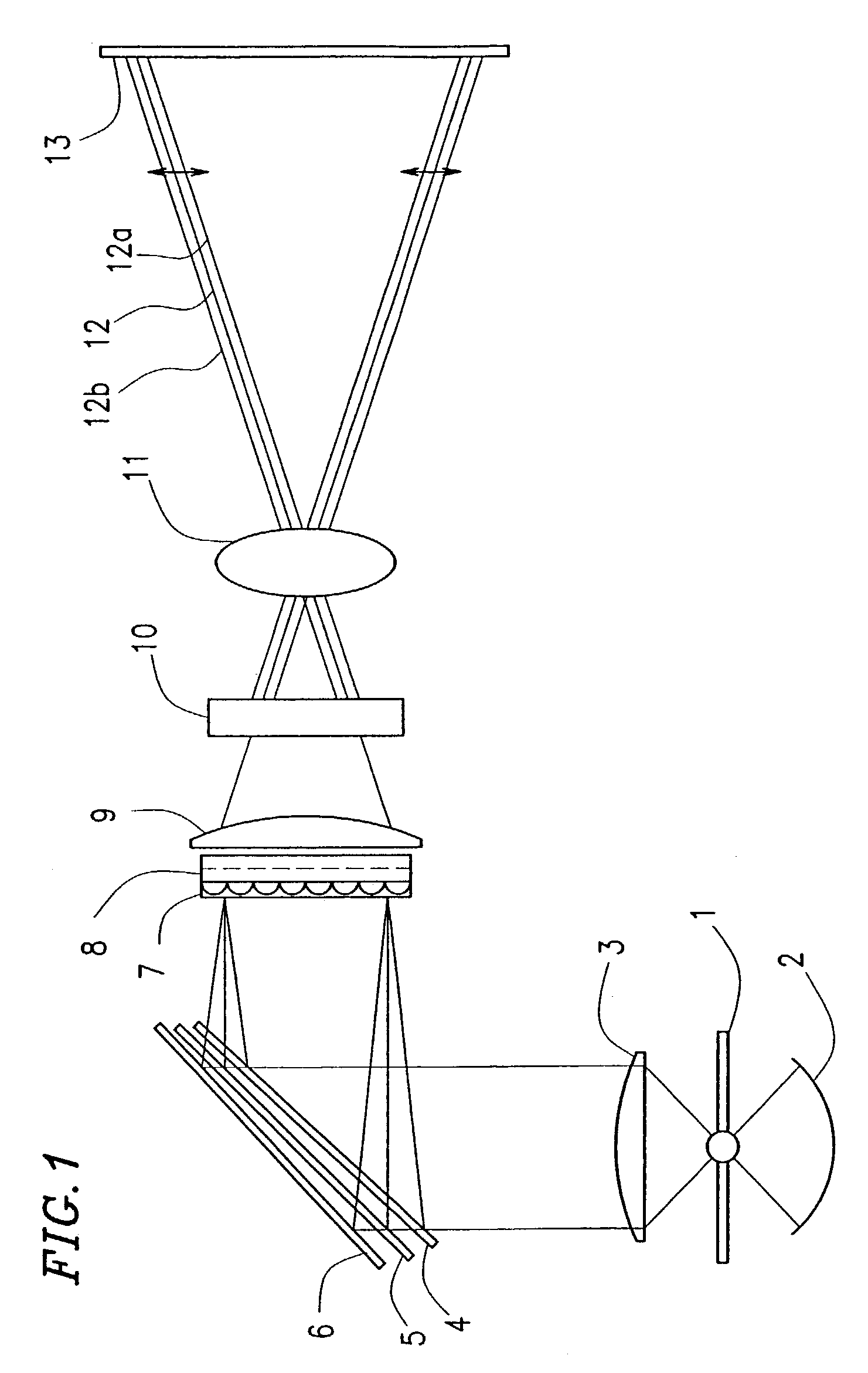
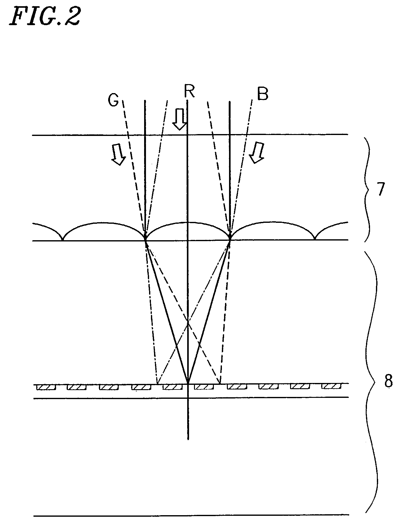
[0076]The optical display system of this embodiment is a projection type. The display system includes a light source 1, an LCD panel 8, light control means and a projection optical system. The light control means is provided to focus the light, emitted from the light source 1, onto associated pixel regions of the LCD panel 8 in accordance with the wavelength ranges thereof. The projection optical system is provided to project the light rays, which have been modulated by the LCD panel 8, onto a projection plane.
[0077]This projection type optical display system further includes a spherical mirror 2, a condenser lens 3 and dichroic mirrors 4, 5 and 6. The spherical mirror 2 reflects the (white) light, which has been emitted backward from the light source 1, forward. The condenser lens 3 collimates the light, which has come from the light source 1 and the spherical mirror 2, into a parallel light beam. Then, the light beam is split by the dichroic mirrors 4, 5 and 6 into a plurality of ...
embodiment 2
[0123]Hereinafter, a second specific preferred embodiment of the present invention will be described. In this preferred embodiment, a stack of half-wave plates is used as the polarization corrector g0 to rotate the polarization direction.
[0124]The achromatic performance is improved by the use of stacked wave plates as disclosed by S. Pancharatnam in “Achromatic Combinations of Birefringent Plates”, Proceedings of Indian Academy of Sciences Vol. XLI, No. 4, Sec. A, 1955, pp. 130–136 and pp. 137–144.
[0125]Specifically, as shown in FIG. 22, the polarization corrector g0 for use in this embodiment includes a first half-wave plate g0A and a second half-wave plate g0B, which are stacked in this order such that the light enters the first half-wave plate g0a earlier than the second half-wavewave plate g0B. To increase the mass productivity, the two half-wave plates g0A and g0B for use in this embodiment are preferably made of the same material and preferably designed to have the same retard...
embodiment 3
[0135]Hereinafter, a third specific preferred embodiment of the present invention will be described. The polarization corrector g0 for use in this third preferred embodiment also includes the first half-wave plate and the second half-wave plate that are stacked in this order such that the first half-wave plate receives the incoming light ray earlier than the second half-wave plate. The material and retardation value of these two half-wave plates may be the same as those adopted for the second preferred embodiment described above. The only difference between the second and third preferred embodiments lies in the slow-axis or fast-axis angles of the half-wave plates.
[0136]In the polarization corrector g0 of this preferred embodiment, the slow axis or fast axis of the half-wave plate on the light incoming side preferably defines an angle of about 67.5 degrees with respect to the vertical direction on the screen. On the other hand, the slow axis or fast axis of the half-wave plate on th...
PUM
 Abstract
Description
Claims
Application Information
 - Generate Ideas
- Intellectual Property
- Life Sciences
- Materials
- Tech Scout
- Unparalleled Data Quality
- Higher Quality Content
- 60% Fewer Hallucinations
Browse by: Latest US Patents, China's latest patents, Technical Efficacy Thesaurus, Application Domain, Technology Topic, Popular Technical Reports.
© 2025 PatSnap. All rights reserved.Legal|Privacy policy|Modern Slavery Act Transparency Statement|Sitemap|About US| Contact US: help@patsnap.com