Microphone apparatus

a microphone and microphone technology, applied in the field of microphone equipment, can solve the problems of univocal louver formation, difficulty for the receiver side to hear the transmitting sound, and (1) inability to solv

Inactive Publication Date: 2006-05-09
VERTEX STANDARD
View PDF2 Cites 3 Cited by
  • Summary
  • Abstract
  • Description
  • Claims
  • Application Information

AI Technical Summary

Benefits of technology

[0026]In accordance with these and other aspects of the invention, the sound box may function as a variable sound filter. In one particular embodiment, the resonant frequency of the adjustable microphone apparatus for guiding sound wave forms between a sound absorbing hole and a sound perceptible portion is changed by the rotational operation of the actuator, whereby making it possible to adjust the variable sound filter to prevent wind noise and breathing sounds and the like from being input to the microphone. Additionally, the adjustment of the variable sound filter can structure the optimal sound input system which is adaptable to even various kinds of prosodic features of the voice.
[0027]In the second embodiment, such variable sound filter acts similarly. However, the resonant frequency of the sound guide system is changed when the movable piece is rotated in the sound box. Thus, the shape of the ventilation channel formed between the respective sound absorbing and sound perceptible holes is changed by the angle of rotation of the movable piece. As a result, the resonant frequency of the entirety of the adjustable microphone apparatus is changed, so as to obtain the similar effect.

Problems solved by technology

However, in the apparatuses used outdoors such as the radio receiver and a transceiver, the following problems occur.
Moreover, since a strong current of air occurs along the front surface of the panel under the strong wind, a space, which is formed between the absorbing hole of the panel and the sound perceptible portion, functions as a column of air or a sound box and a so-called “wind noise” is inputted into the microphone, and this makes it difficult for a receiver side to hear the transmitting sound.
However, since various resonant conditions and sound pressure propagation conditions may be established depending on the state of the sound pressure caused by the uttered sound close to the panel surface and the direction of the wind, univocal louver formation as adopted in measures (1) cannot solve the aforementioned problems.
In addition, it is almost impossible to form an ideal louver.
However, this reduces sensitivity as a sound absorbing system and particularly attenuates high frequency components of voice frequency considerably, thereby deteriorating the reception quality on the receiver side.
There has been experimentally known a problem in which the transmission system does not match a voice with a specific prosodic feature and particularly consonants, which belong to the high frequency, become unclear.

Method used


Image

  • Microphone apparatus
  • Microphone apparatus
  • Microphone apparatus

Examples


first embodiment

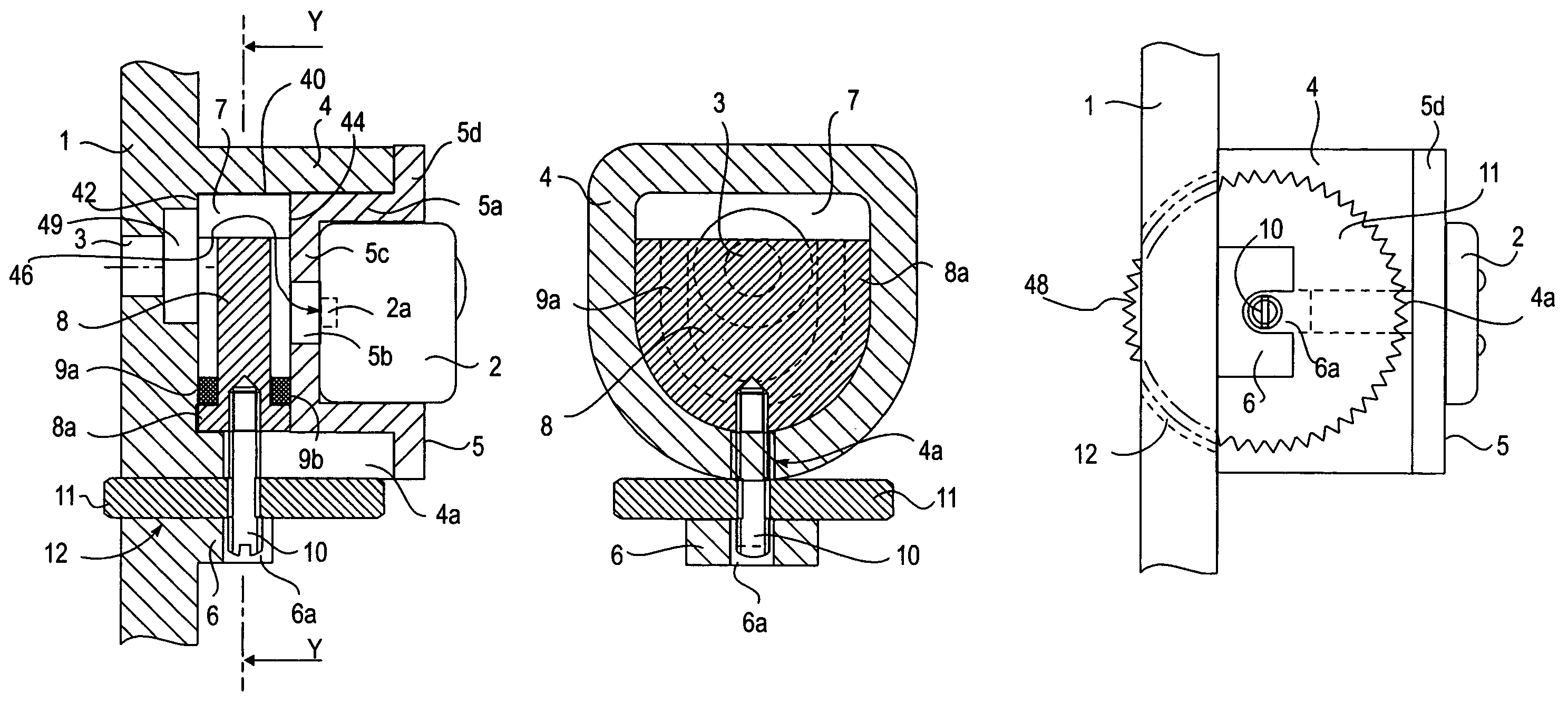
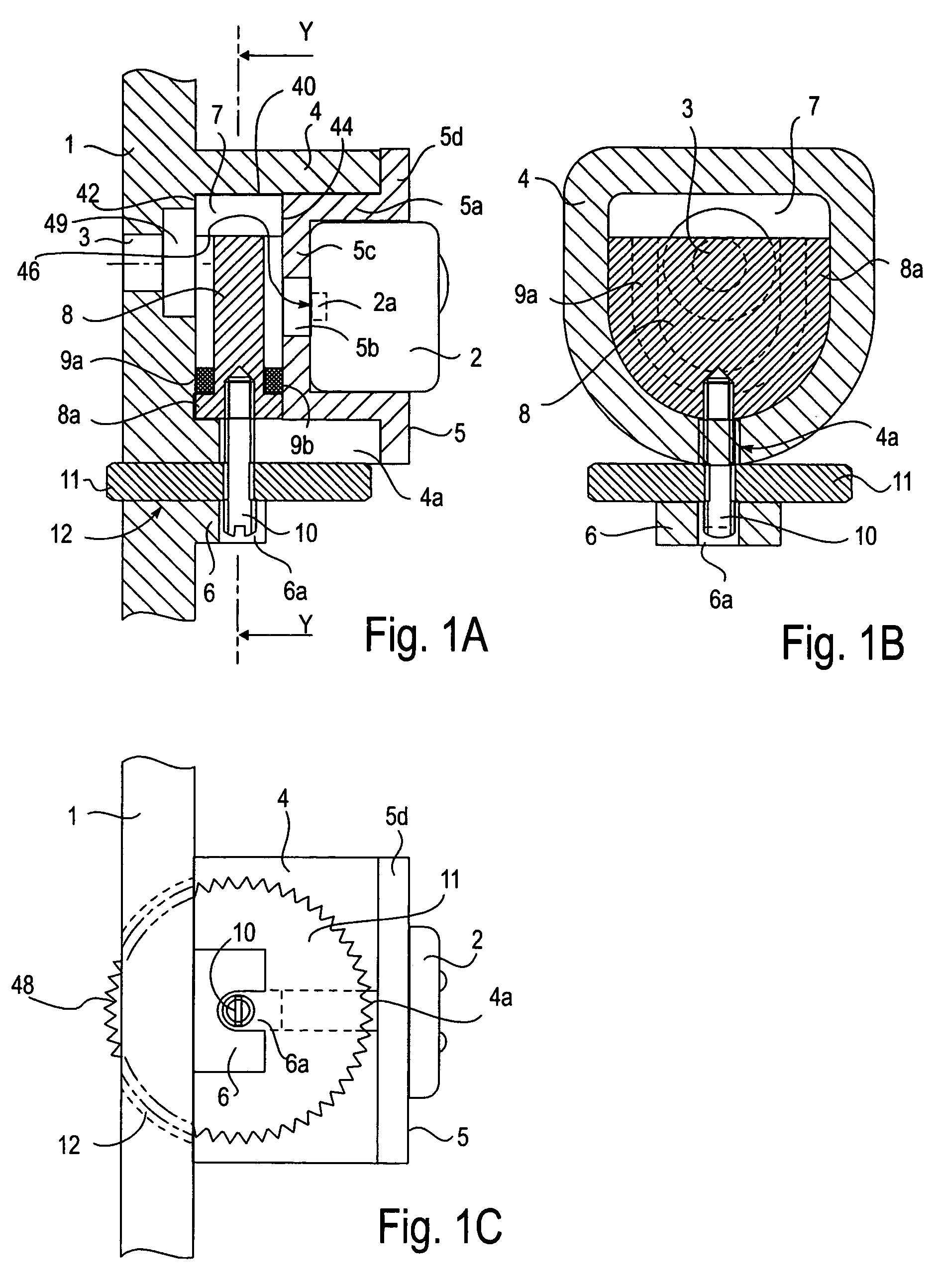
[0037]First, FIG. 1 is a structure diagram illustrating a state in which a microphone is attached to a panel of a microphone case of a mobile-use radio apparatus, (A) is a cross-sectional view, (B) is a perspective cross-sectional view taken substantially along line Y—Y of (A), and (C) is a bottom view.

[0038]In each view, reference numeral 1 denotes a panel, and reference numeral 2 denotes a microphone. A sound absorbing hole 3 is formed on the panel and a tubular portion 4 with substantially a D-shaped cross section is integrally formed at a back surface side of the sound absorbing forming region. The microphone 2 is attached to the tubular portion 4 on the panel 1 through an adapter 5.

[0039]A slot 4a with a fixed width is formed from a rear end side at a lower side wall portion of the tubular portion 4 of the panel 1.

[0040]A support plate 6 is integrally provided at the lower side of the tubular portion 4 of the panel 1 to have a given distance. The support plate 6 is installed in...

second embodiment

[0054]As in the case of the first embodiment, this embodiment will explain, as an example, the microphone apparatus that relates to the microphone case of the radio apparatus.

[0055]In FIG. 4, (A) is a cross-sectional view of the microphone, (B) is a perspective cross-sectional view taken substantially along line Y1—Y1 of (A), (C) is a perspective cross-sectional view taken substantially along line Y2—Y2 of (A), and (D) is a bottom view.

[0056]In each view, reference numeral 21 denotes a panel, 22: a microphone, 23: a sound absorbing hole, 24: a tubular portion, which is integral with the panel 21, and 25: an adapter for attaching the microphone 22 to the tubular portion.

[0057]Here, the tubular portion 24 is formed at the back surface side 52 of the area where the sound absorbing hole 23 is formed in the panel 21. The basic structure, in which the microphone 22 is attached to the tubular portion 24 through the adapter 25, is the same as the first embodiment. The adapter includes an ap...


PUM


Abstract

There is provided a microphone apparatus with an adjusting mechanism that prevents wind noise generated at a sound absorbing hole from perceptively inputted in the structure having a microphone built-in at the back of a panel with a sound absorbing hole.A sound box is structured between a sound absorbing hole of a panel and a sound perceptible portion of a microphone, and a movable piece that slidably moves in the sound box is formed. A screw rod is annexed to the movable piece, and a disk screwed with the screw rod is restricted and interposed between a tubular portion, serving as an outer frame of the sound box, and a support portion formed at the lower portion. A part of the disk is exposed to the front surface side from a slit of the panel, and the disk is rotated to move the movable piece, whereby changing a resonant frequency of a ventilation space of the sound box and a ventilation cross.

Description

[0001]This application is a continuation of U.S. patent application Ser. No. 10 / 442,545, filed on May 21, 2003, now U.S. Pat. No. 6,771,789, which is in turn a continuation of U.S. patent application Ser. No. 09 / 805,307, filed on Mar. 12, 2001, now U.S. Pat. No. 6,590,988, which are incorporated by reference in their entireties.BACKGROUND OF THE INVENTION[0002]1. Field of the Invention[0003]The present invention relates to a microphone apparatus, and more particularly to an acoustic structure, which is applied to a radio apparatus, a recording apparatus and the like in which a microphone is built in a microphone case or a main housing, for resolving the problem in which clarity of voice information to be absorbed is lost by a phenomenon in which transmitting voice with a strong sound pressure or under strong wind, wind noise or prosodic features of voices based on various kinds of languages and individual differences are generated.[0004]2. Description of the Related Art[0005]Convent...

Claims


Application Information

Patent Timeline
Patent Type & Authority Patents(United States)
IPC IPC(8): H04R11/04H04R1/34H04R1/08H04R1/28
CPCH04R1/083
Inventor KAKINUMA, HIDEAKI
Owner VERTEX STANDARD
Why Eureka
Try Eureka