Swipe imager with multiple sensing arrays

Inactive Publication Date: 2006-05-09
ACTIVCARD IRELAND
View PDF10 Cites 82 Cited by
  • Summary
  • Abstract
  • Description
  • Claims
  • Application Information

AI Technical Summary

Problems solved by technology

In general, there are two types of errors associated with fingerprint identification.
A Type II error occurs when there are enough similarities between fingerprints of two individuals, that one is mistaken for the other.
A Type I error occurs for a variety of reasons, and refers to when an individual is not identified even though the individual is an authorized user registered with the system.
It has been suggested that the underlying cause of errors in fingerprint analysis is that the amount of data from a fingerprint is too limited for it to be used in a biometric identification system involving a large number of users.
Alternatively, poor performance of fingerprint verification systems is attributed to the fact that the final verification decisions are based upon comparisons of small isolated regions of the fingerprint, when in fact a small sampling of the ridges does not provide enough detail to accurately verify or identify an individual.
Furthermore, the analysis of pore prints generally obviates the fraudulent problems encountered with fingerprint identification, since latent fingerprints do not generally contain a lot of detail about pore size, shape and/or distribution.
Consequently, the use of latent fingerprints, which often fools most fingerprint identification systems, does not deceive pore print identification systems.
An optical/electronic sensor capable of providing a high resolution fingerprint image is required for extraction of pertinent pore information, which makes it unlikely that electronically scanned inked fingerprints would contain adequate pore data that is sufficient, or consistent enough, for use in authentication.
Although the prior art clearly benefits from pore print technology, it does not truly exploit

Method used


Image

  • Swipe imager with multiple sensing arrays
  • Swipe imager with multiple sensing arrays
  • Swipe imager with multiple sensing arrays

Examples


second embodiment

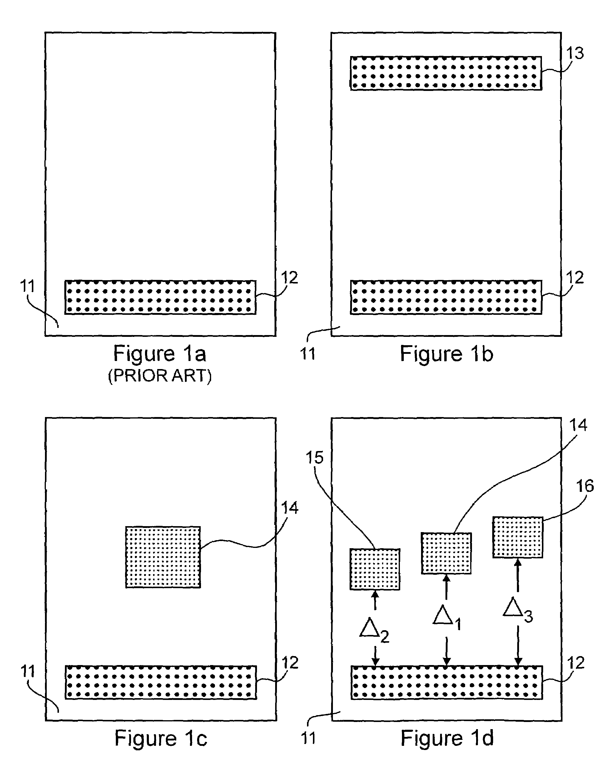
[0048]In FIG. 1c, a simplified block diagram of an imaging device according to the present invention is shown. The sensing pad 11 comprises two linear capacitive sensing arrays 12 and 14, which now have a different number of sensing elements. In this example, the linear capacitive sensing array 12 comprises 10 rows and 200 columns, whereas the linear capacitive sensing array 14 comprises 20 rows and 20 columns. Preferably, the linear sensing array 12 has a first resolution, and the linear sensing array 14 has a same resolution. Alternatively, the linear sensing array 12 has a first resolution, and the linear sensing array 14 has a second, other resolution. The same interleaving functionality as described for the imaging device of FIG. 1b is also performed by the device described in FIG. 1c. Here the larger images are interleaved with the help of the small images offset therefrom by other than an integer multiple of a line spacing, which allows for more accurate alignment of images. ...

third embodiment

[0049]In FIG. 1d, a simplified block diagram of an imaging device according to the present invention is illustrated. The sensing pad 11 comprises a linear capacitive sensing array 12 and three small capacitive sensing arrays 14, 15 and 16. In this example, the linear capacitive sensing array comprises 10 rows and 200 columns, whereas each of the small linear capacitive sensing arrays comprises 20 rows and 20 columns. The first small linear capacitive sensing array 14 is spaced apart from the linear capacitive sensing array by a distance Δ1=(N+½)·δ1. Again, δ1 stands for the row spacing of the linear capacitive sensing device 12, and N is an integer. The second small linear capacitive sensing array 15 is spaced apart form the capacitive sensing array 12 by a distance Δ2=(N+¼)·δ1, whereas the third small linear capacitive sensing array 16 is spaced apart by a distance Δ3=(N+¾)·δ1. This way, through interleaving of the series of partial images retrieved by the imaging device, a four-fo...

tenth embodiment

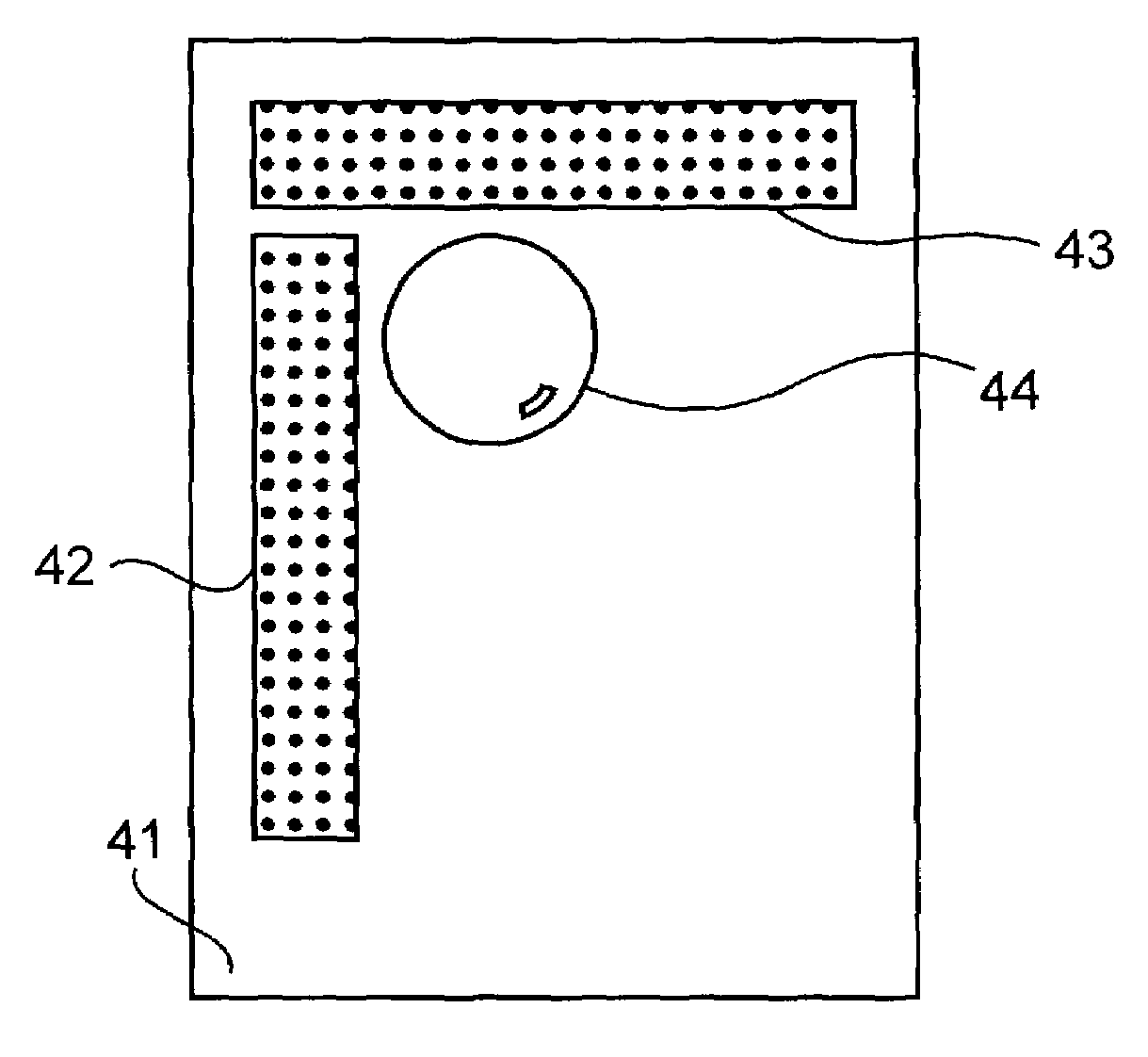
[0065]the present invention is now described with reference to FIG. 4. The sensing pad 41 comprises a first longitudinal linear capacitive sensing array 42 having 10 rows and 200 columns, and a second latitudinal linear capacitive sensing array 43 comprises 200 rows and 10 columns. The array 43 is arranged in a way that its rows are parallel to the rows of array 42, and the array 43 is aligned at one of the edges of the array 42. Thus, the two sensing arrays are arranged to substantially form a right angle. In this modification, a motion sensor in form of a track ball 44 is added to the overall system. The trackball 44 is connected to a processor for processing the motion data provided from the motion sensor. The motion sensor reduces an amount of redundant information that the sensing pad 41 captures, provides additional information for image construction, and allows for sensing of a moving surface regardless of direction or type of motion. Thus, for example, the linear capacitive ...


PUM


Abstract

A biometric sensing device includes sensing arrays for sensing a biological surface swiped across the sensing arrays in an arbitrary direction. This device allows for simultaneously sensing different features of a biological surface where the features have the smallest distinguishable features of different size. Using the technique of interleaving partial images, the resolution of the biometric sensing device is increased. Therefore, a small and robust biometric sensing device is provided, which allows for sensing high resolution images.

Description

[0001]This application claims benefit from U.S. Provisional Application Nos. 60 / 300,836 filed on Jun. 27, 2001; 60 / 305,186 filed on Jul. 16, 2001; 60 / 305,910 filed on Jul. 18, 2001; and 60 / 306,139 filed on Jul. 19, 2001.FIELD OF THE INVENTION[0002]This invention relates generally to imaging devices and more particular to devices suitable for identification of an individual from an examination of their fingerprint characteristics and the like.BACKGROUND OF THE INVENTION[0003]Fingerprint analysis is amongst the most widely used and studied biometric techniques. During the last two decades, many new and exciting developments have taken place in the field of fingerprint science, summarized for example in the monograph Advances in Fingerprint Technology, 2nd ed., edited by H. C. Lee and R. E. Gaensslen (CRC Press, 2001). Fingerprint identification not only plays a major role in forensic or police science, but also in controlling the building-access or information-access of individuals to...

Claims


Application Information

Patent Timeline
IPC IPC(8): G06K9/00
CPCG06K9/00026G06K9/0002G06V40/1335G06V40/1306
Inventor HAMID, LAURENCEASHDOWN, SCOTT NEWMAN
Owner ACTIVCARD IRELAND
Why Eureka
Try Eureka