Method and apparatus for maintaining accurate positioning between a probe and a DUT

a technology of accurate positioning and dut, which is applied in the direction of mechanical measuring arrangements, instruments, and mechanical means, etc., can solve the problems of dut drift and/or probe dri

Active Publication Date: 2006-05-16
MICROMANIPULATOR +1
View PDF10 Cites 62 Cited by
  • Summary
  • Abstract
  • Description
  • Claims
  • Application Information

AI Technical Summary

Benefits of technology

[0010]It will be understood that while the method and apparatus are described with respect to a high resolution viewing system employing a vacuum chamber for testing operations, the present invention could be implemented in other testing environments. In addition, the probe station herein includes significant flexibility in allowing both the probe and the DUT to be shifted either together or independent from each other. Further, the probe is connected to a probe manipulator assembly that allows for further shifting of the probe independent of the platen on which it is supported. Manifestly, the present drift compensation method and apparatus can be utilized where only the probe or DUT is shifted to the test position, or where the probe is not connected to a manipulator such as with probe cards. Accordingly, while it is the positions of both the probe and the DUT that is monitored where both can be shifted, where one or the other is fixed against movement and thus drift, the present method and apparatus can be implemented to monitor and compensate for the drift of the component that is shifted to the predetermined test position, which usually will be the probe. Nevertheless, it is the position of the probe relative to the fixed DUT that is monitored in this instance so that even where the DUT is fixed the amount of drift that is monitored is the drift of the probe relative to the DUT and away from the test position. Accordingly, herein the terms “relative” or “test” position refers to the position of the probe and DUT relative to each other such as when they are positioned properly for testing operations, whether one or the other is fixed, or both can be shifted.

Problems solved by technology

In this instance, heat generated during operation of motor drives for shifting of the probe or DUT, or both, to the test position can cause drift of the probe and / or DUT.

Method used


Image

  • Method and apparatus for maintaining accurate positioning between a probe and a DUT
  • Method and apparatus for maintaining accurate positioning between a probe and a DUT
  • Method and apparatus for maintaining accurate positioning between a probe and a DUT

Examples


Embodiment Construction

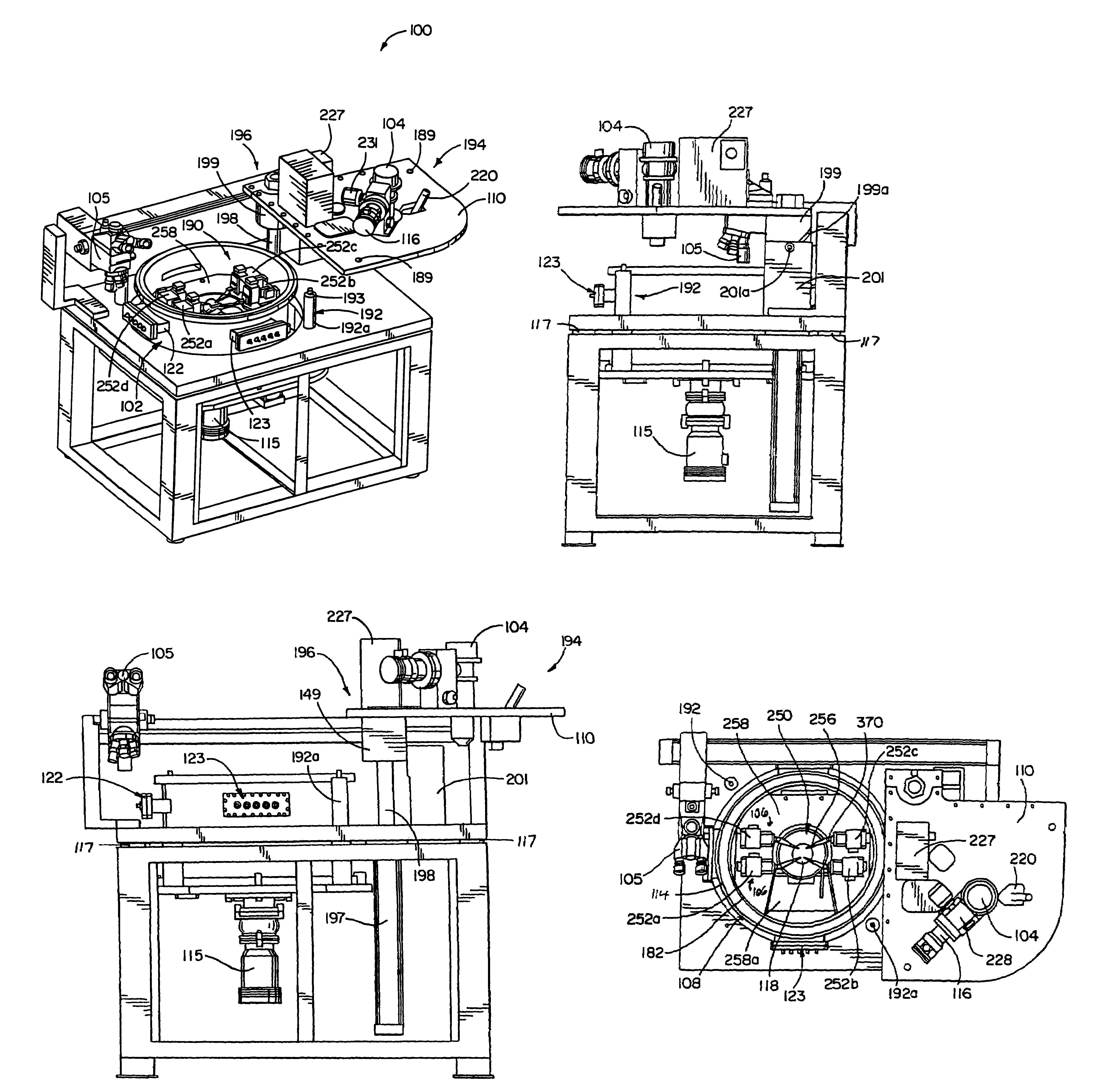
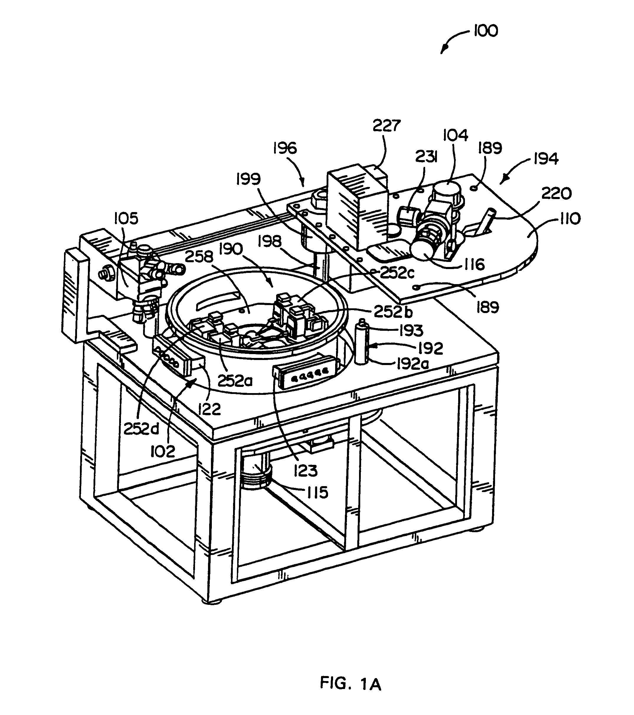
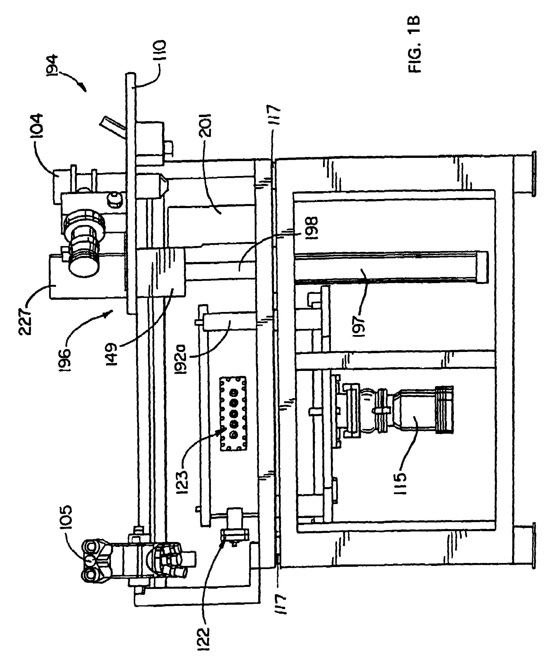
[0034]A method and apparatus for keeping a probe accurately positioned relative to a device to be tested is disclosed herein. The method and apparatus herein determine if there is a variance between the current probe position and the desired or predetermined probe position, (e.g., drift), and then correct the position of the probe, if deemed necessary. In addition to a probe, the apparatus has a movable probe station element for positioning the probe at a predetermined test position on the specimen. The probe station element includes a drive that is operable to position the probe at the test position, and a controller substantially keeps the probe at the test position and avoids having the probe shift away therefrom. The controller includes software programmed to determine the variance (or drift) between the current probe position and the desired or predetermined test position, and actuates the drive after the variance has reached a predetermined value in order to generally maintain...


PUM


Abstract

A method and apparatus for keeping a probe accurately positioned relative to a device to be tested. The apparatus having a probe and movable probe station element for positioning the probe at a predetermined test position on the device to be tested. The probe station element being driven by a drive to position the probe at the test position, and having a controller connected thereto for substantially keeping the probe at the test position and inhibiting the probe shifting therefrom. In one form the controller is capable of determining the variance between the current probe position and the desired or predetermined test position, and actuating the drive after the variance has reached a predetermined value.

Description

CROSS-REFERENCE TO RELATED APPLICATION[0001]This application claims the benefit of U.S. Provisional Application No. 60 / 525,300, filed Nov. 26, 2003, which is hereby incorporated herein by reference in its entirety.REFERENCE TO COMPUTER PROGRAM LISTING APPENDIX SUBMITTED ON A COMPACT DISC[0002]The computer program listing appendix contained within file “driftset.txt” on compact disc “1 of 1”, which has been filed with the United States Patent and Trademark Office in duplicate, is hereby incorporated herein by reference. This file was created on Jul. 27, 2003, and is 27.4 KB in size.[0003]A portion of the disclosure of this patent document contains material which is subject to copyright protection. The copyright owner has no objection to the facsimile reproduction by anyone of the patent document or the patent disclosure, as it appears in the Patent and Trademark Office patent file or records, but otherwise reserves all copyright rights whatsoever. See MPEP §608.01(v).BACKGROUND OF TH...

Claims


Application Information

Patent Timeline
Patent Type & Authority Patents(United States)
IPC IPC(8): G01B5/004G01C15/00
CPCG01R31/2891G01R1/025
Inventor HOLLMAN, KENNETH F.SCHMIDT, STEPHEN W.
Owner MICROMANIPULATOR
Why Eureka
Try Eureka