Turbocharger

a technology of turbocharger and turbine wheel, which is applied in the direction of liquid fuel engines, machines/engines, stators, etc., can solve the problems of loss of energy for rotating the turbine wheel, loss of energy when recovering the dynamic pressure, etc., and achieve the effect of preventing exhaust interference and increasing the flow rate of exhaust gases

Inactive Publication Date: 2006-05-16
KOMATSU LTD
View PDF25 Cites 21 Cited by
  • Summary
  • Abstract
  • Description
  • Claims
  • Application Information

AI Technical Summary

Benefits of technology

[0028]By this, since a pulse converter is provided in the exhaust inflow passage inside the turbocharger, a compact constitution is obtained. Further, by the pulse converter, an interference between the exhaust gases introduced from the inlets in two places can be reduced. Additionally, since a dynamic pressure can be effectively converted into a static pressure, a loss of energy for rotating the turbine wheel becomes small.
[0030]In the turbocharger concerning the invention, a distance between the throttle inlet to the throttle outlet may be made 20–40% of a distance from the throttle inlet to a rear end of the tongue part. By this, it is possible to prevent the exhaust interference by sufficiently increasing flow velocities of the exhaust gases and, since the diffuser part is long, the dynamic pressure can be effectively converted into the static pressure.

Problems solved by technology

Additionally, since a dynamic pressure can be effectively converted into a static pressure, a loss of energy for rotating the turbine wheel becomes small.
By this, the loss of the energy when recovering the dynamic pressure as the static pressure becomes small.

Method used


Image

  • Turbocharger
  • Turbocharger
  • Turbocharger

Examples


Embodiment Construction

[0044]Hereunder, embodiments concerning the invention are explained in detail while referring to the drawings.

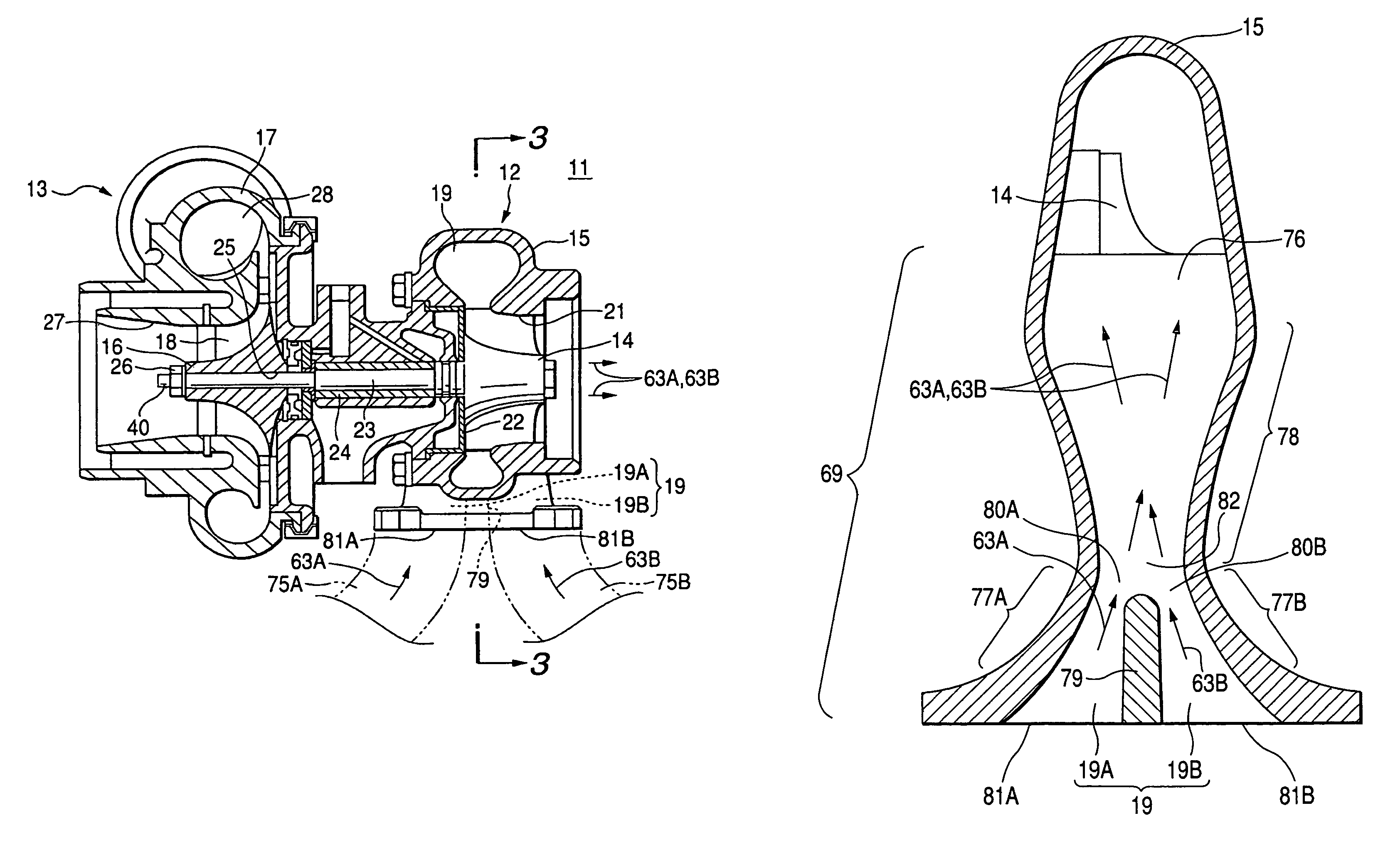
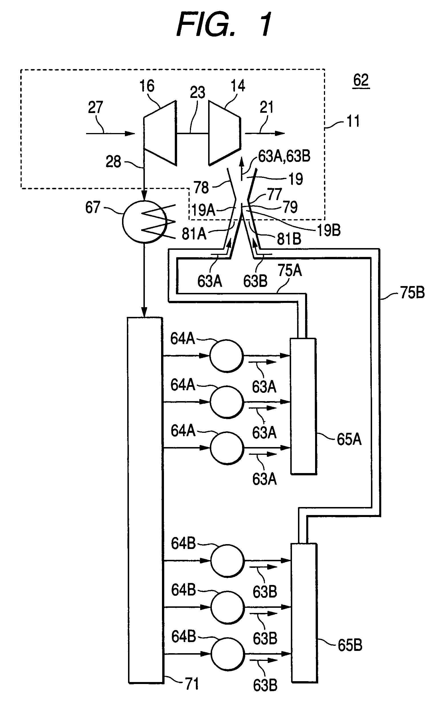
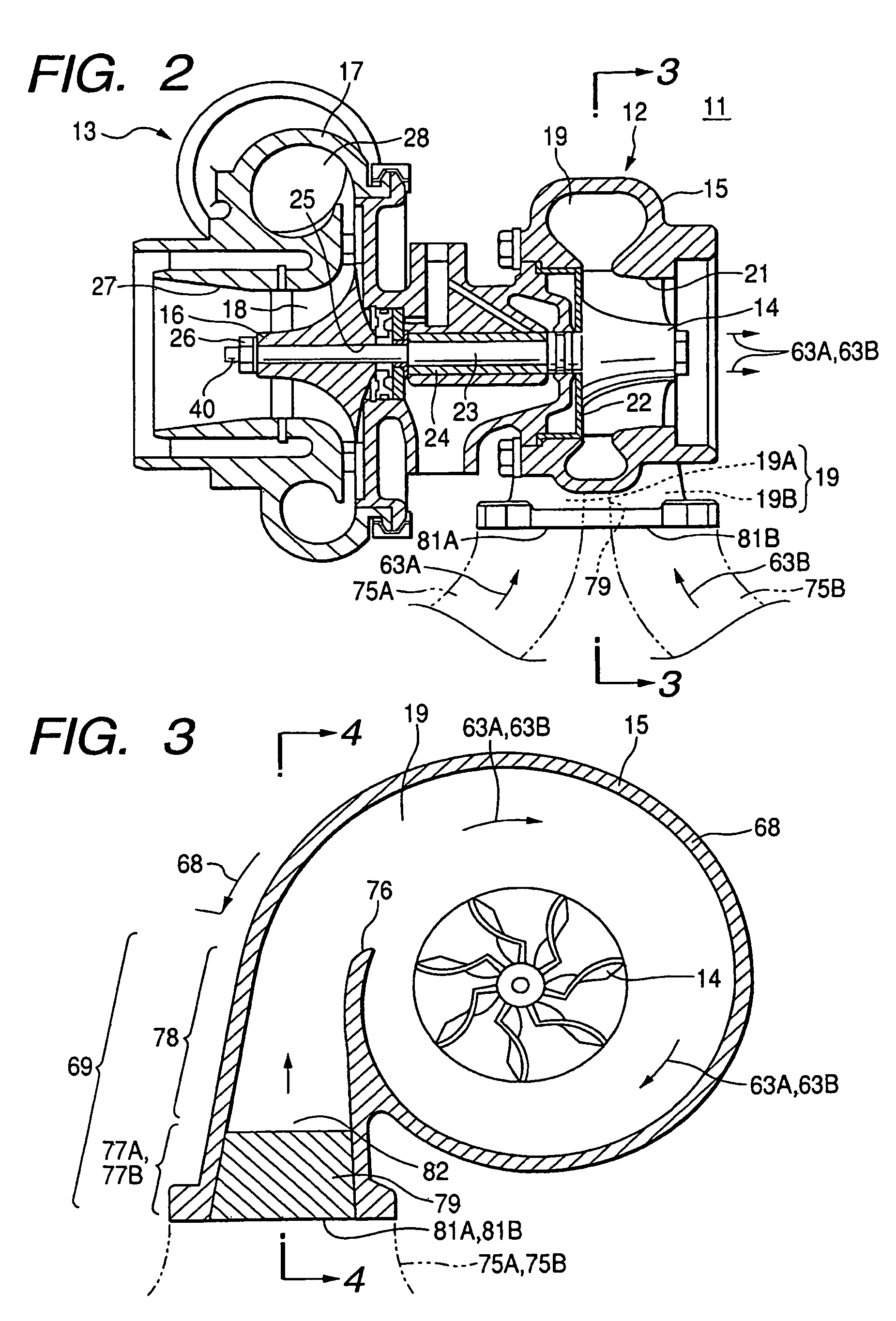
[0045]First, a 1st embodiment is explained. It is an example of an engine that does not use an EGR system. As shown in FIG. 1 to FIG. 4, the exhaust piping 75A, 75B are respectively connected to the front / rear exhaust manifolds 65A, 65B. The introduction part 69 of the exhaust inflow passage 19 is bisected from its inlets 81A, 81B to its approximately halfway part into the two exhaust inflow passages 19A, 19B by a partition part 79. And, the exhaust piping 75A, 75B are respectively connected to inlets 81A, 81B of the exhaust inflow passages 19A, 19B.

[0046]The exhaust gases 63A, 63B exhausted from the front / rear cylinder groups 64A, 64B respectively flow into the inlets 81A, 81B of the two exhaust inflow passages 19A, 19B while passing through the front / rear exhaust manifolds 65A, 65B and the front / rear exhaust piping 75A, 75B. And, the exhaust gases 63A, 63B are joined at a ...


PUM


Abstract

There is provided a turbocharger whose constitution is compact, in which exhaust interference seldom occurs, and which can be applied also to an EGR type engine. In the turbocharger, an introduction part of an exhaust inflow passage possesses a partition part dividing a range from an inlet to a predetermined position in a downstream of the inlet into two exhaust inflow passages, a throttle part, whose sectional area becomes gradually small, from the inlet to a position where the partition part ceases, a joining part where exhaust gases passing through the left and right exhaust inflow passages are joined, and a diffuser part, whose sectional area becomes gradually large, from the joining part to a tongue part.

Description

BACKGROUD OF THE INVENTION[0001]1. Field of the Invention[0002]The present invention relates to a turbocharger.[0003]2. Description of the Related Art[0004]From old times, as means increasing a charge amount of engine, there has been known a turbocharger compressing the air and charging it to the engine by rotating a turbine wheel by utilizing an energy of exhaust gas, and driving a compressor wheel of a centrifugal type through a shaft formed monolithically with the turbine wheel.[0005]In FIG. 7, there is shown a piping system diagram of an engine using the turbocharger concerning the prior art. It is explained with a straight 6-cylinder engine 62 being taken as an example. The engine 62 possesses six cylinders 64A, 64B linearly arranged. The six cylinders 64A, 64B are classified into the upside three cylinders 64A and the downside three cylinders 64B. The upside cylinders 64A are referred to as front cylinder group 64A, and the downside cylinders 64B are referred to as rear cylind...

Claims


Application Information

Patent Timeline
Patent Type & Authority Patents(United States)
IPC IPC(8): F02B37/02F02B37/00F01D9/06F01D9/00F01D9/02F02B29/04F02B39/00F02C6/12F02M25/07
CPCF01D9/026F02B29/0406F02B37/02F02B37/025F02C6/12F02M26/43F02M26/05F02M26/23Y02T10/12F01D9/00F02B37/00
Inventor NISHIYAMA, TOSHIHIKOSUGITO, HIROSHIIINO, TAKAHISAOGAWA, TETSUAKI
Owner KOMATSU LTD
Why Eureka
Try Eureka