System and method for imaging and decoding optical codes using at least two different imaging settings

a technology of optical codes and imaging settings, applied in the field of imaging and decoding of optical codes, can solve the problems of inability to accurately decode image data by decoding software, and possibility of one or more unsuccessful reads

Inactive Publication Date: 2006-05-16
SYMBOL TECH LLC
View PDF13 Cites 88 Cited by
  • Summary
  • Abstract
  • Description
  • Claims
  • Application Information

AI Technical Summary

Benefits of technology

[0014]In accordance with another embodiment of the present invention, an optical code reader system for reading an optical code is provided. The system includes an imaging engine having a lens assembly and a photo sensor array for consecutively imaging an optical code located in a field of view of the imaging engine using at least a first and a second imaging setting, and means for generating at least first and second sets of image data respectively corresponding to the first and second imaging settings. The system further includes at least one processor for evaluating at least one of the first and second sets of image data, and selecting at least one of the first and second sets of image data in accordance with the evaluation. Computer code executable by the at least one processor for processing the first and / or second sets of image data, including evaluating and selecting in accordance with the evaluation, may be stored on a computer readable medium or transmitted via a propagated data signal embodied in a transmission medium.

Problems solved by technology

Unsuccessful reads result when the quality of image data is lacking and the decoding software is unable to accurately decode the image data.
In applications where optical codes are read and decoded quickly, such as in rapid succession, if the time consumed for receiving the image data, processing the image data, decoding the image data and outputting the decoded code exceeds the time interval until a next set of image data is received, a possibility exists for one or more unsuccessful reads, such as misreads or no reads to occur.
However, the code may have to be re-imaged after the determination and appropriate action have been performed, resulting in a repetitious and lengthy procedure.

Method used


Image

  • System and method for imaging and decoding optical codes using at least two different imaging settings
  • System and method for imaging and decoding optical codes using at least two different imaging settings
  • System and method for imaging and decoding optical codes using at least two different imaging settings

Examples


first embodiment

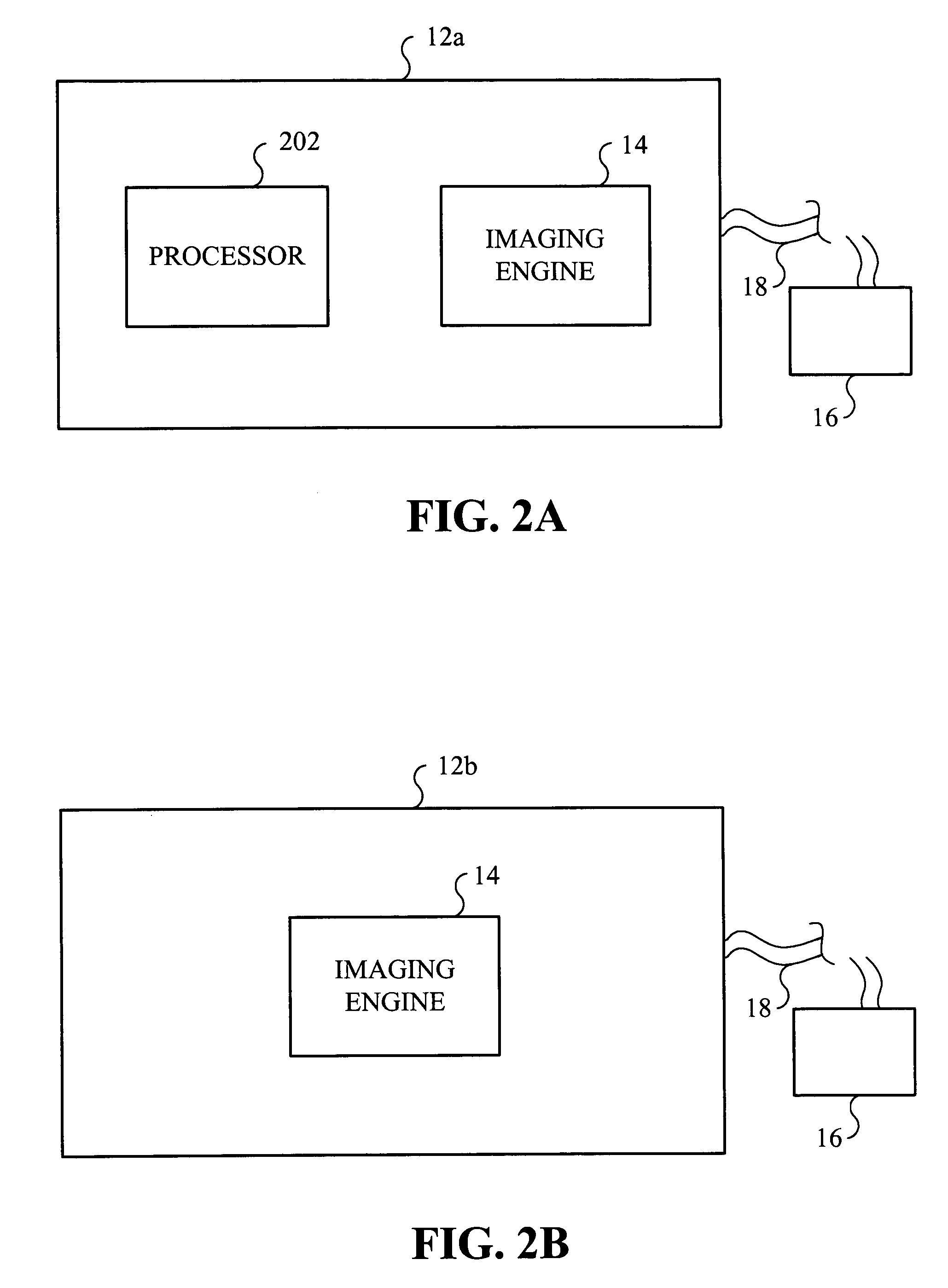
[0034]FIG. 2A is a block diagram of a reader 12a in accordance with the present invention. As shown, the reader 12a includes the imaging engine 14 and a processor 202. The imaging engine 14 is responsive to control signals generated by the processor 202, host terminal 16 and / or actuating means to image an optical code positioned in a field of view currently aimed at by the imaging engine 14 using at least a first and second set of configuration settings for generating respective first and second sets of image data. The first and second sets of image data are processed by at least one of the processor 202 and an external processor included in the host terminal 16 for analyzing and decoding the first and second sets of image data in combination to obtain a decoded code that corresponds to the optical code.

second embodiment

[0035]FIG. 2B is a sectional view of a reader 12b in accordance with the present invention. The reader 12b includes the imaging engine 14 which is responsive to the host terminal 16 and / or actuating means to image an optical code positioned within a field of view currently aimed at by the imaging engine 14 using the first and second set of configuration settings for generating respective first and second sets of image data. The first and second sets of image data are transmitted via cable 18 and processed by the host terminal 16 for analyzing and decoding the first and second sets of image data in combination to obtain a decoded code that corresponds to the optical code. Reader 12b does not include a processor for processing the image data, and the image data is transmitted via cable 18 to one or more processors, such as an external processor in host terminal 16 for exclusive processing thereof.

Imaging Engine

[0036]With reference to FIG. 3, the imaging engine 14 is shown to include a...


PUM


Abstract

A system and method for imaging an optical code is provided including the steps of consecutively imaging an optical code respectively using at least a first and a second imaging setting; generating at least first and second sets of image data respectively corresponding to the first and second imaging settings; evaluating at least one of the first and second sets of image data; and selecting at least one of the first and second sets of image data in accordance with the evaluation. The system includes an imaging engine having a lens assembly and a photo sensor array for consecutively imaging an optical code located in a field of view of the imaging engine using at least the first and the second imaging settings, and generating the at least first and second sets of image data respectively corresponding to the first and second imaging settings. The system further includes at least one processor for evaluating the at least one of the first and second sets of image data, and selecting the at least one of the first and second sets of image data in accordance with the evaluation.

Description

PRIORITY[0001]This application claims priority to a United States Provisional Application filed on Dec. 18, 2002 and assigned U.S. Provisional Application Ser. No. 60 / 434,519, the contents of which are incorporated herein by reference.BACKGROUND OF THE INVENTION[0002]1. Field of the Invention[0003]This invention relates to imaging and decoding of optical codes, and particularly to imaging and decoding an optical code using first and second imaging settings and decoding the optical code using image data corresponding to the first and second imaging settings.[0004]2. Description of the Related Art[0005]Optical codes are patterns made up of image areas having different light reflective or light emissive properties, which are typically assembled in accordance with a priori rules. The optical properties and patterns of optical codes are selected to distinguish them in appearance from the background environments in which they are used. A barcode is an optical code having a pattern of vari...

Claims


Application Information

Patent Timeline
Patent Type & Authority Patents(United States)
IPC IPC(8): G06K7/10G02B7/04G02B7/09G06K7/00G06K19/14G06V30/10
CPCG06K7/0004G06K7/0008G06K7/10386G06K19/14G06K7/10811G06K9/726G06K7/10722G06V30/274G06V30/10
Inventor PATELLU, KEFEIGOREN, DAVID P.HATTON, EDWARDVANDE VYVRE, BRUNOJOSEPH, EUGENECARLSON, BRADLEY S.
Owner SYMBOL TECH LLC
Why Eureka
Try Eureka