Magnetic latch system

a magnetic latch and latch technology, applied in the field of magnetic latches, can solve the problems that the magnetic latch system does not allow for the easy opening of the gate, and achieve the effect of simple, reliable and robus

Active Publication Date: 2006-05-16
DEUT BANK AG NEW YORK BRANCH AS COLLATERAL AGENT
View PDF39 Cites 44 Cited by
  • Summary
  • Abstract
  • Description
  • Claims
  • Application Information

AI Technical Summary

Benefits of technology

[0004]In view of the foregoing, it should be apparent that a need still exists in the art for a locking device that avoids the problems inherent in the prior art systems. Accordingly, it is a primary object of the present invention to provide an improved magnetic lock assembly which is of a simple, reliable, robust and reversible construction and in which, during unlatching, the keeper pin is positively moved away from the permanent magnet in the latch assembly by way of an internal lever operable from either side of the gate.
[0005]The latch of the present invention may be used to replace latches that are typically spring or gravity activated. Spring and gravity activated locks have some resistance to latching and require a force to be applied to the gate to get it “past” the latching mechanism to fully latch. It is then gravity or the spring that keep the mechanism latched. With the present invention, there is no substantial force required to latch. In fact, it is quite the opposite in that the magnet actually pulls the gate closed once the gate is nearly closed. This “positive latching” operation is a substantial advantage over the spring and gravity locks.

Problems solved by technology

This prior art magnetic latch system does not allow for the easy opening of the gate from the front and / or the back side of the gate.

Method used


Image

  • Magnetic latch system
  • Magnetic latch system
  • Magnetic latch system

Examples


Embodiment Construction

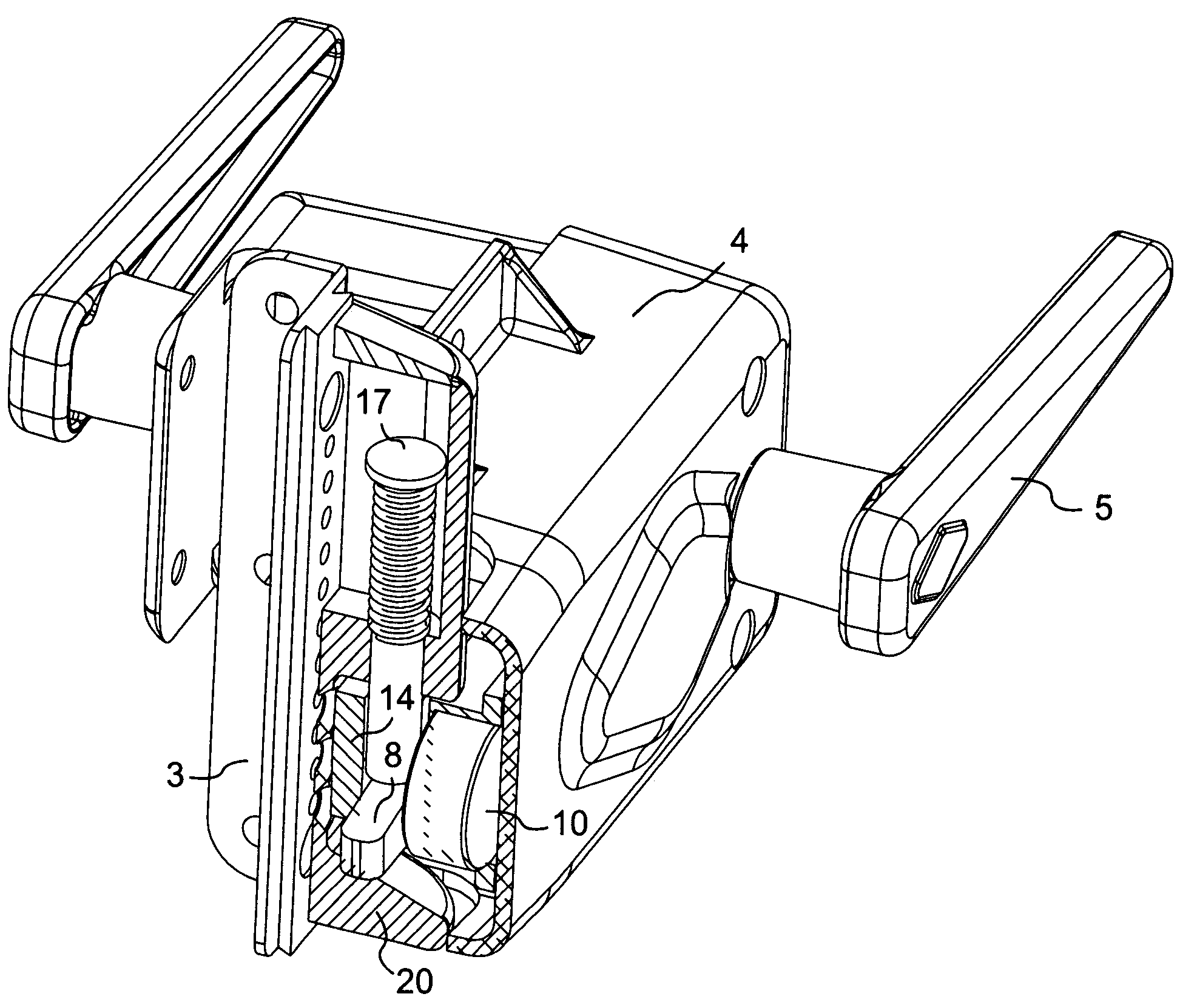
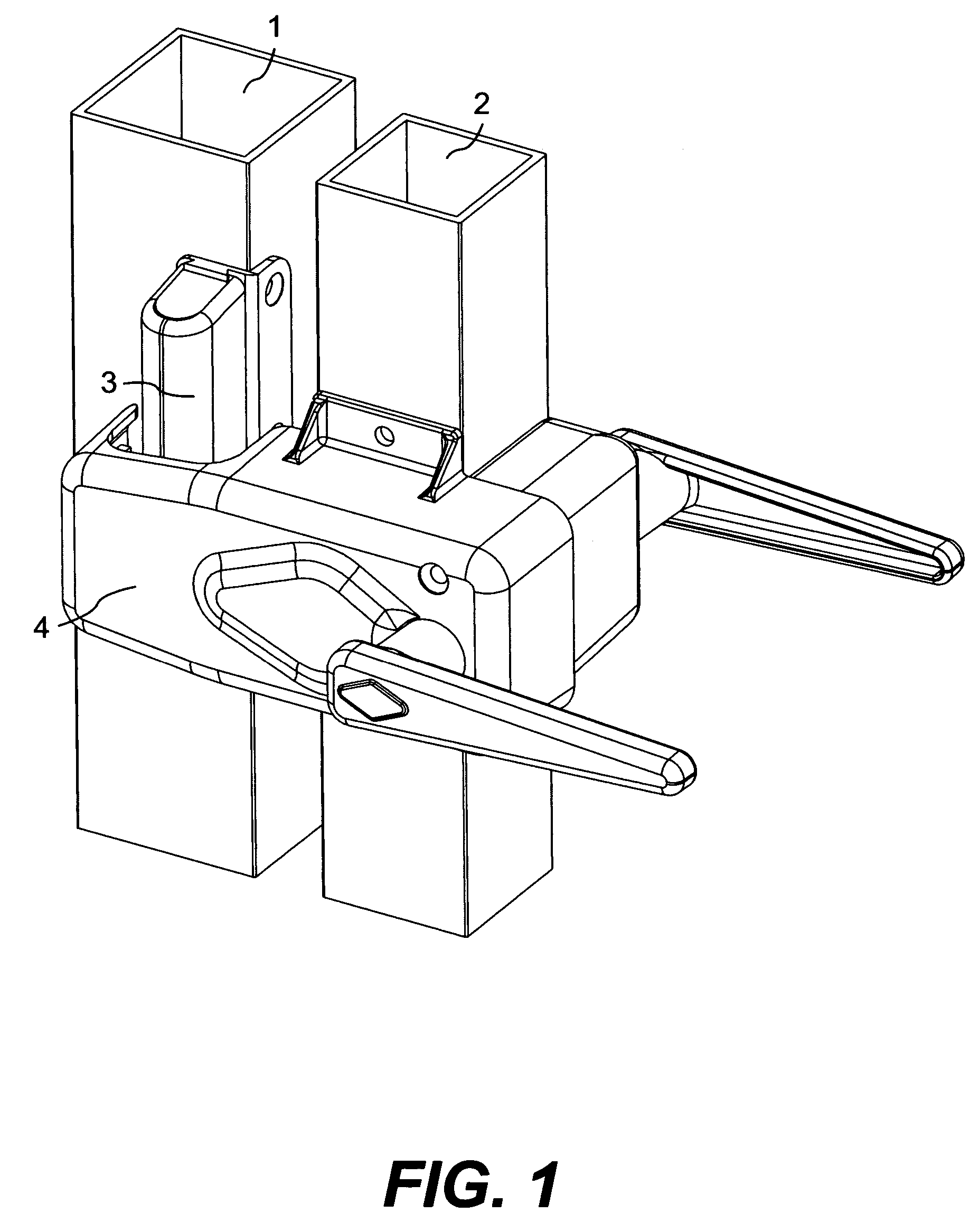
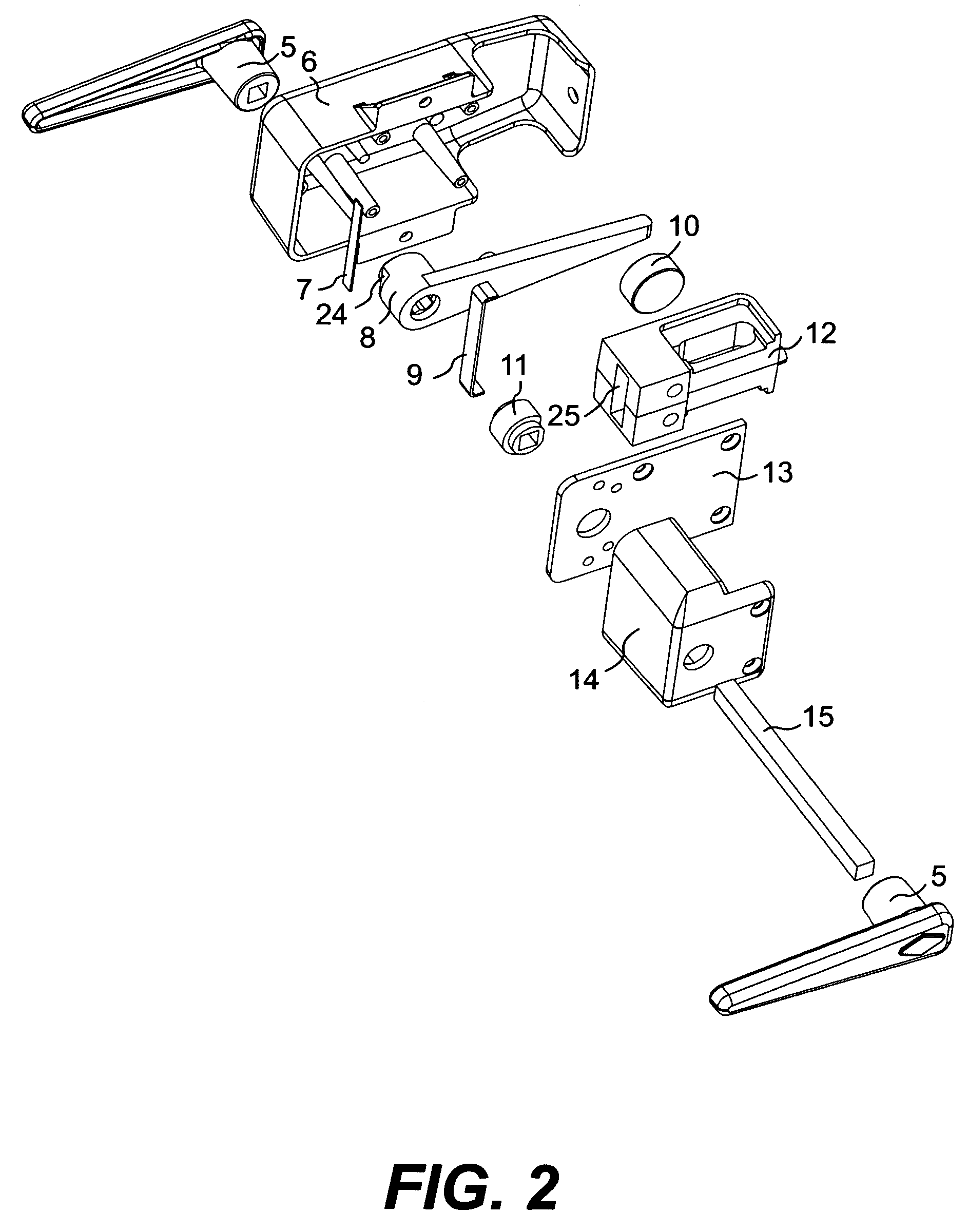
[0036]FIG. 1 of the drawings shows the magnetic latch assembly of the present invention including the latch assembly 4 which is mounted on to the gate post 2 and the keeper assembly 3 which is mounted to the fence post 1. FIG. 1 depicts the magnetic latch assembly and gate and fence post in a closed and latched position. FIG. 2 of the drawings shows an exploded view of the latch assembly 4 more generally depicted in FIG. 1. Handles 5 are mounted to either end of the spindle 15. The spindle 15 is mounted through the front housing 6, back cover 13 for the front housing and back housing 14. The internal lever 8 and spindle spring bushing 11 are mounted on the spindle 15 inside of the housing components when the assembly is arranged. A lever spring 7 acts upon a flat surface 24 on the internal lever 8 and acts to bias the internal lever 8 into a horizontal position. A handle spring 9 acts on a flat spot 16 on the spindle spring bushing 11 to bias the handles 5 into a horizontal position...


PUM


Abstract

A magnetic latch system including a latch assembly and a keeper assembly. The keeper assembly includes a magnetically attractable keeper pin. The latch assembly includes a magnet and a movable internal lever which is arranged to engage the keeper pin to move it away from the permanent magnet. The system may also include a lock to hold the internal lever in a fixed position so that it cannot be moved to move the keeper pin away from the magnet.

Description

RELATED APPLICATIONS[0001]This application is based upon the magnetic latch disclosure found in U.S. Provisional Application Ser. No. 60 / 560,967 filed Apr. 12, 2004.FIELD OF THE INVENTION[0002]The present invention relates to a magnetic latch and, more particularly, to a magnetic latch system useful for latching a gate to a fence post.BACKGROUND ART[0003]U.S. Pat. No. 5,362,116 discloses a magnetic latch system which is self latching in a predetermined position. The system includes a latch arm mounted on one gate member (e.g., post). The latch arm is movable between a latched and a retracted position. The system also includes a retaining element incorporating a permanent magnet and adapted to be mounted on a second gate member (e.g., gate). The latch arm is spring biased into the retracted position but, when it is located over the magnet, it is caused to move by the magnetic field of the magnet into a latched position wherein the latch arm engages the retaining element. In order to ...

Claims


Application Information

Patent Timeline
Patent Type & Authority Patents(United States)
IPC IPC(8): E05C17/56E05C3/04E05C19/16
CPCE05C19/163Y10T292/11Y10T292/18
Inventor KLIEFOTH, CHRISTOPHERTIMOTHY, E. ERIK
Owner DEUT BANK AG NEW YORK BRANCH AS COLLATERAL AGENT
Why Eureka
Try Eureka