
Cemented electrode joint and process for curing the same

a technology of cement electrode and joint, which is applied in the field of graphite electrode, can solve the problems of all the remainder of the electrode, falling into the molten steel mixture, and electrode cracking, and achieve the effect of resisting breaking and cracking and stable electrode column

Inactive Publication Date: 2006-09-07
GRAFTECH INT HLDG INC
View PDF5 Cites 6 Cited by
  • Summary
  • Abstract
  • Description
  • Claims
  • Application Information

AI Technical Summary

Benefits of technology

[0011] It is an aspect of the present invention to provide a graphite electrode joint that resists breaking and cracking during use, providing a more stable electrode column.
[0012] It is another aspect of the present invention is to provide a graphite electrode joint having improved resistance to stub loss.
[0013] It is yet another aspect of the invention to provide a method for adhering two electrodes together, which is simple, reliable and robust.
[0018] The cement is cured by attaching positive and negative terminals across the joint. When power is supplied, current travels across the joint thereby curing the cement. Advantageously, if this curing process is short enough, the curing process may be conducted on-furnace, thereby reducing furnace down-time and maximizing furnace operation. Alternatively, if so desired, the curing process may be done on the shop floor.

Problems solved by technology

Around its circumference and at the top, near the joint, chemical oxidation and mechanical forces attack the electrode, causing it to weaken, crack and / or break, which may cause some or all of the remainder of the electrode, sometimes referred to as a “stub,” to fall into the molten steel mixture.
Sometimes, the electrode cracks or becomes damaged due to the harsh shaking within the furnace that exists due to furnace operation; again, this may result in an electrode stub falling into the molten steel mixture.
The joint between two electrodes in a column is one of the weakest points in the electrode column; thus, it is especially susceptible to degradation and / or breakage.
When an electrode stub falls into the molten steel mixture, it adds an impurity to the mix and, because the electrode is not completely used up in its desired current carrying capacity, it results in inefficient electrode consumption.
However, the conventional cement curing processes are time-consuming and cause expensive delays in furnace operation.
Known curing processes are also disadvantageous because the curing process was necessarily performed on the shop floor, i.e., “off-furnace,” rather than over the furnace, i.e., “on-furnace.” The known curing processes that require the cement to be cured on the shop floor require the graphite electrode column to be moved from its location within the furnace to a predetermined area on the shop floor.
While the electrode column is on the shop floor, it cannot be used to melt steel and thus the furnace is either not functioning or doing so at a less than desirable rate.
However, electrodes having opposing male and female ends are also known and the joint between these two types of electrodes are also susceptible to damage and / or breakage resulting in stub loss.

Method used


Image

  • Cemented electrode joint and process for curing the same
  • Cemented electrode joint and process for curing the same
  • Cemented electrode joint and process for curing the same

Examples


Embodiment Construction

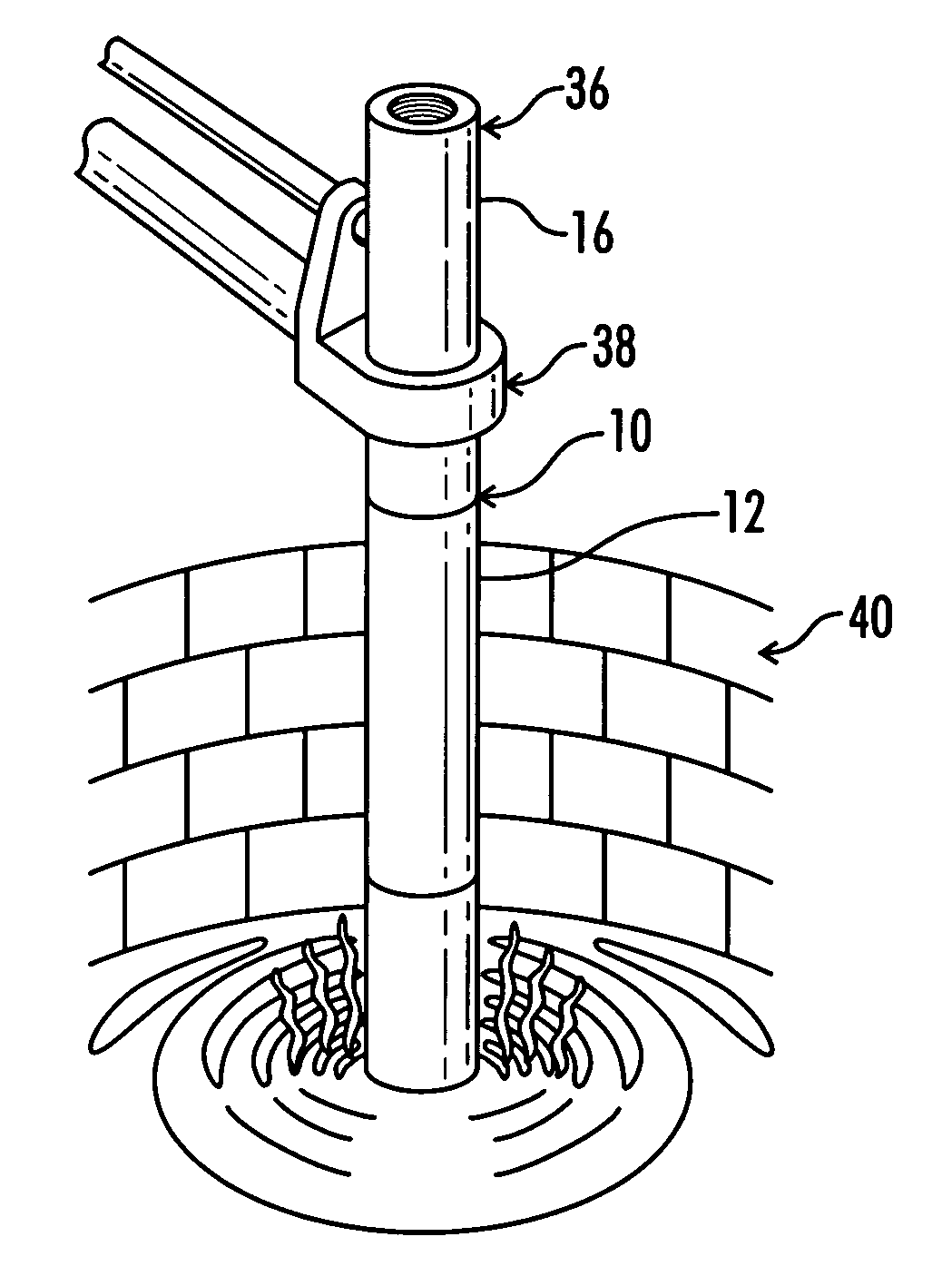
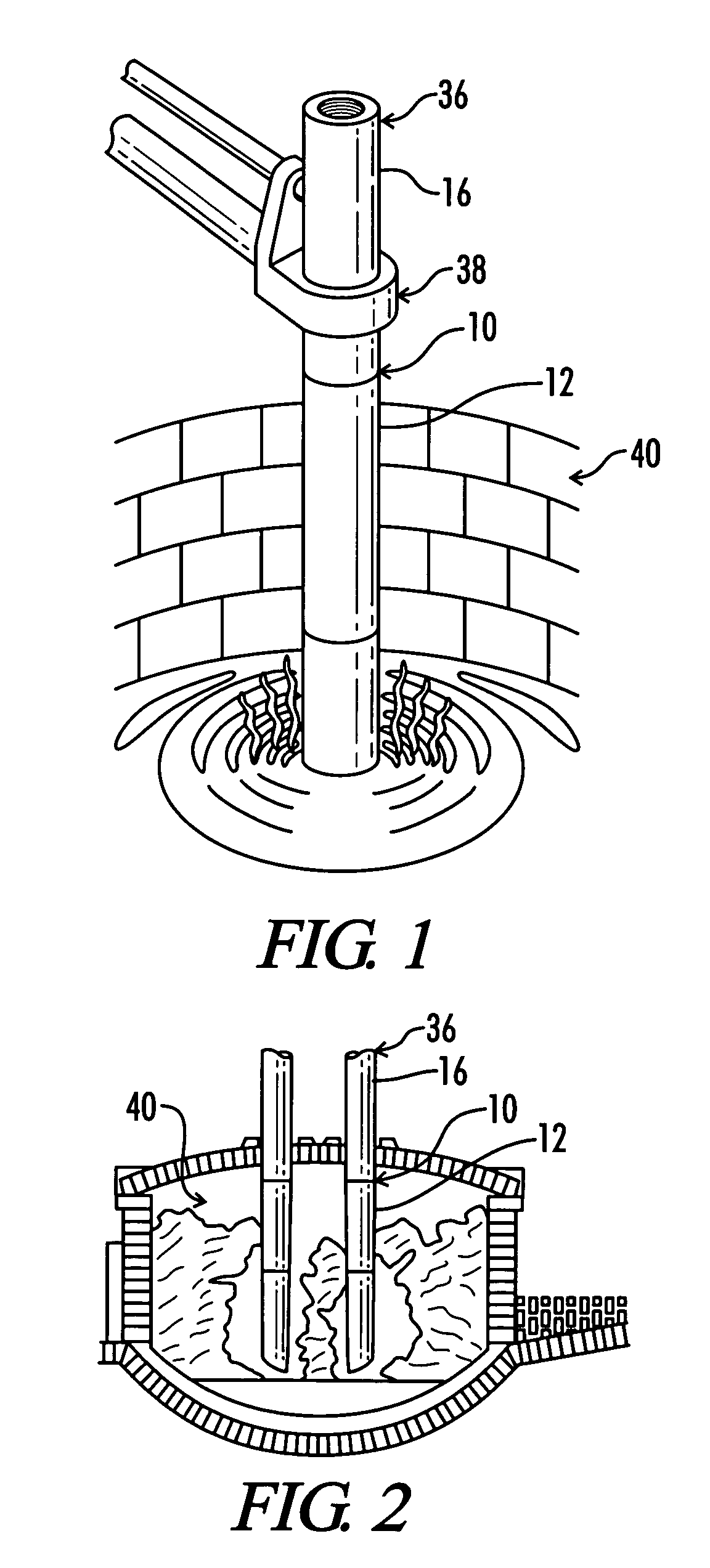
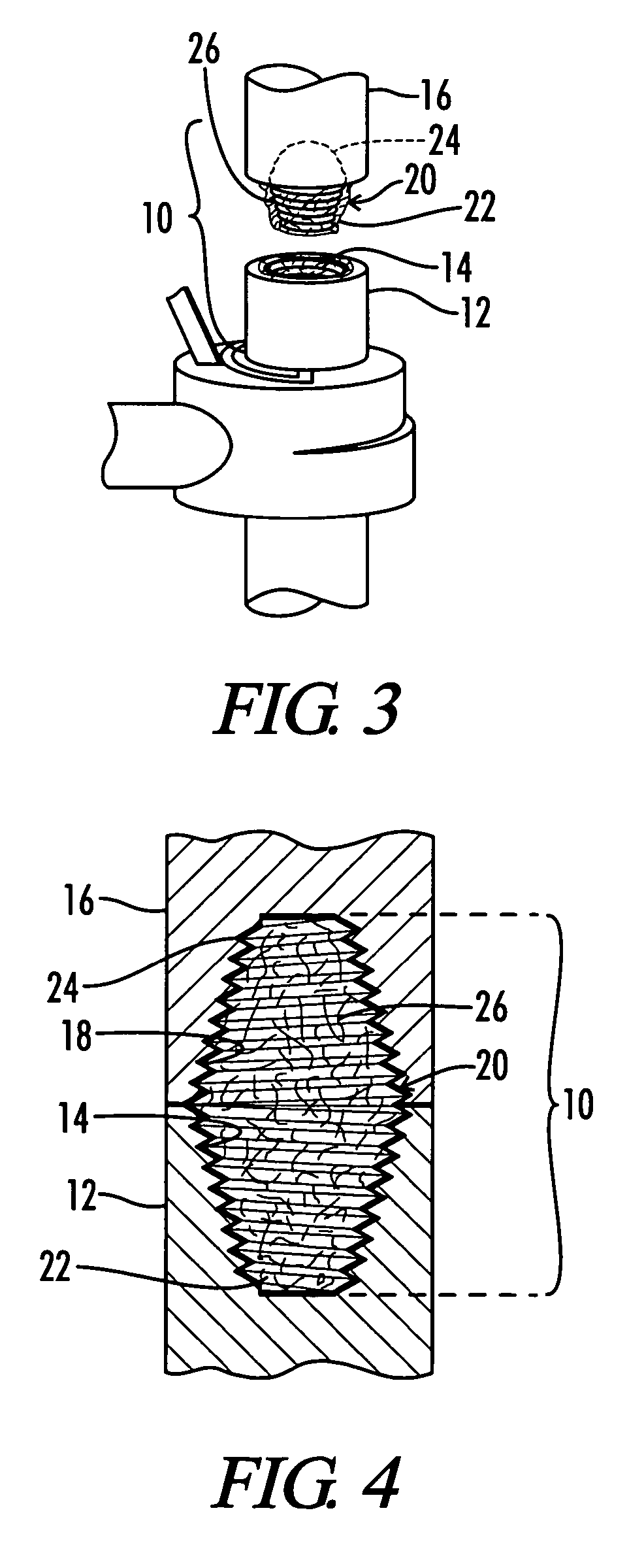
[0027] An electrode joint constructed in accordance with the present invention is generally shown by the reference numeral 10 and illustrated in FIG. 1. The electrode joint 10 is formed when a carbon body 12, such as a graphite electrode, having at least one female end 14 (best shown in FIG. 3) is connected to another carbon body 16, such as a graphite electrode, having at least one female end 18. See FIGS. 1, 3, 4. As best shown in FIGS. 3, 4, a pin 20 having at least two male ends 22, 24 is used to mate with the female ends 14, 18 of the first and second electrodes 12, 16, thereby forming joint 10 therebetween.

[0028] To desirably connect the electrodes 12, 16 at the joint 10, the present invention teaches the use of a thermally-curing adhesive material or mixture 26, which is inserted at least partially into and / or around the area of the joint 10. See FIGS. 3-6. Any suitable thermally-curing adhesive may be used. In the most preferred embodiment, the material comprises cement. In...


PUM

PropertyMeasurementUnit
heat lossaaaaaaaaaa
electrical currentaaaaaaaaaa
AC electrical currentaaaaaaaaaa

Abstract

A graphite electrode joint and method for forming the graphite electrode joint, wherein the method includes the steps of providing a first graphite electrode having at least one end; providing a second graphite electrode having at least one end; applying a thermally-curing adhesive material, such as cement, on one or more of the graphite electrodes at or near the ends thereof; joining together the first and second graphite electrodes having thermally-curing adhesive material thereon at their respective ends so as to form a joint therebetween; and curing the cement by passing electrical current across the joint.

Description

BACKGROUND OF THE INVENTION TECHNICAL FIELD [0001] The present invention relates to carbon bodies, especially graphite electrodes, and a method for joining the graphite electrodes with improved stability. More particularly, the invention relates to a unique process for curing cemented electrode joints. BACKGROUND ART [0002] In the steel industry, graphite electrodes are used in electrothermal furnaces, sometimes called electric arc furnaces, to melt metals and other ingredients to form steel. The heat needed to melt metals is generated by passing current through one or more electrodes and forming an arc between the electrode(s) and the metal in the furnace. Electrical currents in excess of 100,000 amperes are often used. The resulting high temperature melts the metals and other ingredients. Generally, the electrodes used in steel furnaces each consist of graphite electrode columns, that is, a series of individual electrodes joined to form a single column. In this way, as electrodes ...

Claims


Application Information

Patent Timeline
Patent Type & Authority Applications(United States)
IPC IPC(8): H05B7/06
CPCH05B7/14Y02P10/25
Inventor INTERMILL, ALLANBOWMAN, BRIANVARELA, WILLIAM
Owner GRAFTECH INT HLDG INC
Learn More