Valve apparatus

a valve and valve body technology, applied in mechanical devices, multiple-way valves, generators/motors, etc., can solve the problems of inefficient fluid cycling, low efficiency of fluid cycling, so as to achieve energetically efficient fluid cycling and disturbances during fluid switching, the effect of reducing losses and large cross sectional area

Inactive Publication Date: 2010-05-13
ABB RES LTD
View PDF9 Cites 6 Cited by
  • Summary
  • Abstract
  • Description
  • Claims
  • Application Information

AI Technical Summary

Benefits of technology

[0025]The valve apparatus of the fourth aspect of the invention provides for energetically efficient cycling of fluid and disturbances during fluid switching are minimized. If the single outlet has large cross sectional area the losses are low.
[0026]The valve apparatus may be provided with an output wherein different portions across the cross section thereof have different fluid path lengths so that any introduced phase delays across the cross section of the outlet can be compensated for. The valve apparatus is particularly suited to be used in a single-phase magnetothermal generator system.

Problems solved by technology

A problem of such arrangement is that energetically inefficient cycling of fluid is achieved and that disturbances during fluid switching occur.
Another limitation is that the frequency of the thermal cycling is limited.
Further, the switch valve of JP 7107764 may not be optimally designed for different kinds of thermomagnetic generator systems.
The cost per net power produced by a generator system featuring the known switch valve may not be optimum.

Method used


Image

  • Valve apparatus
  • Valve apparatus
  • Valve apparatus

Examples


Embodiment Construction

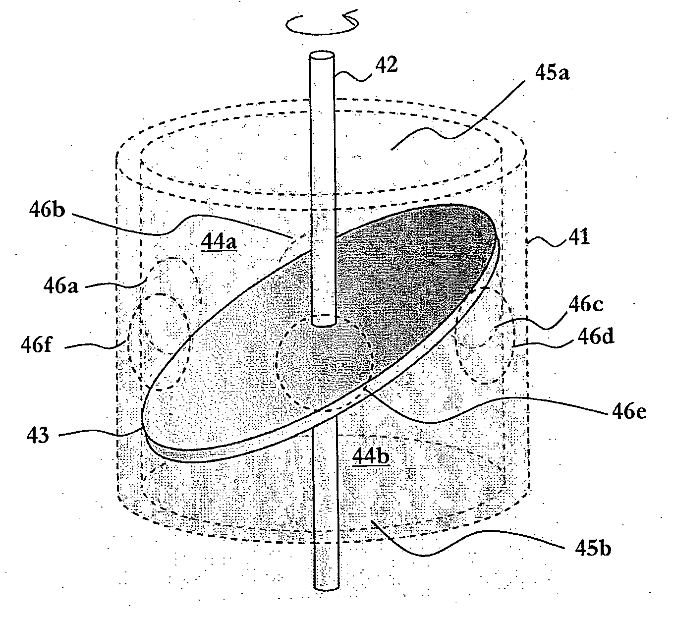
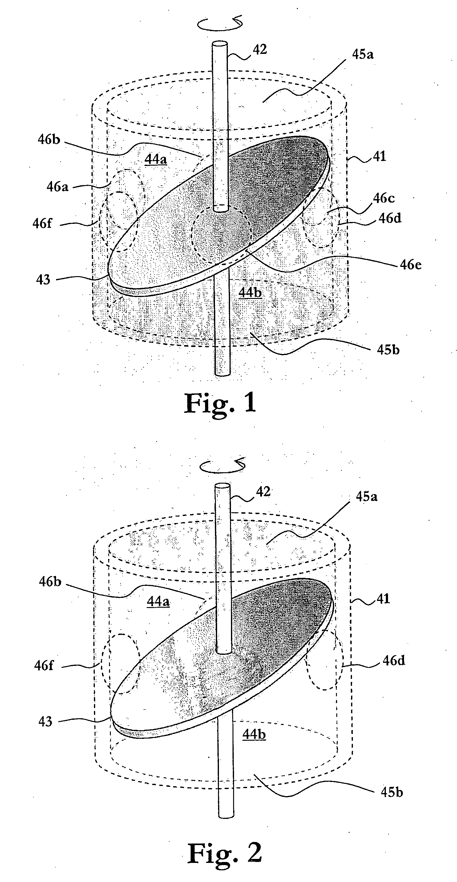
[0035]A rotating valve apparatus according to an embodiment of the invention is disclosed in FIG. 1. A hollow cylinder or cylindrical casing 41 houses a symmetrically arranged rotatable shaft 42, to which a member 43 is fixedly attached. The member 43, which preferably is thermally isolating, is provided in close fit with the cylindrical casing 41 and defines a first and a second identical compartment or chamber 44a-b of the apparatus. The member 43 is an elliptic disc fixedly mounted on the shaft 42 at an axial position and with an inclination angle such that each of the outlets 46a-f at the circumference of the cylindrical casing 41 is alternately in fluid connection with the chambers 44a-b as the shaft 42 and the elliptic disc 43 are rotated with respect to the cylindrical casing 41.

[0036]The elliptic plate might be fabricated by cutting it from a solid cylinder having a diameter slightly less than the inner diameter of the cylindrical casing.

[0037]Alternatively, the member 43 ha...


PUM


Abstract

A rotating valve apparatus including a cylindrical casing, a shaft arranged symmetrically in the casing, a member fixedly attached to the shaft and in close fit with the cylindrical casing, defining separated chambers within the casing, at least one outlet fixedly arranged along the circumference of the casing and a plurality of axially arranged inlets, each of which is constantly in fluid communication with a respective one of the separated chambers. The axially arranged inlets are alternately in fluid connection with the outlet fixedly arranged along the circumference of the casing in response to rotation of the shaft and the member with respect to the casing. The member has an elliptically shaped cross section.

Description

TECHNICAL FIELD OF THE INVENTION[0001]The present invention generally relates to valve apparatuses. The invention is preferably, but not exclusively, intended for a generator system for converting thermal energy to electric energy.DESCRIPTION OF RELATED ART AND BACKGROUND OF THE INVENTION[0002]In known generator systems for converting thermal energy to electric energy there is provided a magnetic circuit of a suitable magnetic material and a coil arranged around the magnetic circuit. A temperature-varying arrangement varies the temperature of the magnetic circuit alternately above and below a phase transition temperature such as the Curie point to thereby vary the reluctance of the magnetic circuit and the magnetization of the magnetic circuit is modulated by the varying reluctance so as to induce electric energy in the coil arranged around the magnetic circuit. The temperature-varying arrangement passes alternately hot and cold fluid by the magnetic circuit and comprises typically ...

Claims


Application Information

Patent Timeline
Patent Type & Authority Applications(United States)
IPC IPC(8): H01L37/04F16K5/00
CPCF16K11/0853Y02E10/34H02N11/002H01L37/04Y02E10/30H10N15/20
Inventor RUSSBERG, GUNNARDAHIGREN, MIKAELTHORBURN, STEFANROTHMAN, BENGT
Owner ABB RES LTD
Why Eureka
Try Eureka