Locking mechanism for a vehicle seat

a technology for locking mechanisms and vehicles, applied in the direction of movable seats, roofs, transportation and packaging, etc., can solve the problem that the intercepting component cannot reach the end position, and achieve the effect of small operating forces

Active Publication Date: 2006-05-16
KEIPER SEATING MECHANISMS CO LTD
View PDF27 Cites 69 Cited by
  • Summary
  • Abstract
  • Description
  • Claims
  • Application Information

AI Technical Summary

Benefits of technology

[0005]Because the at least one securing element secures an opened state by interaction with a second functional surface of the pawl, with the at least one securing element exerting an opening moment on the pawl in this opened state, complete opening is ensured, in particular also in comparison to solutions in which a dead center or friction has to be overcome. This prevents states in which although the mating element can come out of a partially opened hook mouth of the pawl, it cannot engage in it again due to tolerances or a bearing clearance. In addition, the solution according to this aspect of the invention makes it possible to design the inherent prestress (e.g., biasing) of the pawl to be weaker, so that smaller operating forces are necessary. The opening moment is achieved preferably in a manner which is structurally simple to realize by the surface normal of the second functional surface (e.g., an imaginary straight line that extends normal to the second functional surface) running between the axis of rotation of the pawl and that region of the pawl, for example a hook mouth or a toothing, which interacts with the mating element. The at least one securing element bears against the second functional surface in a preferably tangential manner by means of a bearing surface, so that the opening moment is applied in a defined direction.

Problems solved by technology

Even in the case of unfavorable tolerances, the intercepting component cannot then be prevented from reaching its end position due to a radially increasing region of the intercepting surface.

Method used


Image

  • Locking mechanism for a vehicle seat
  • Locking mechanism for a vehicle seat
  • Locking mechanism for a vehicle seat

Examples


Embodiment Construction

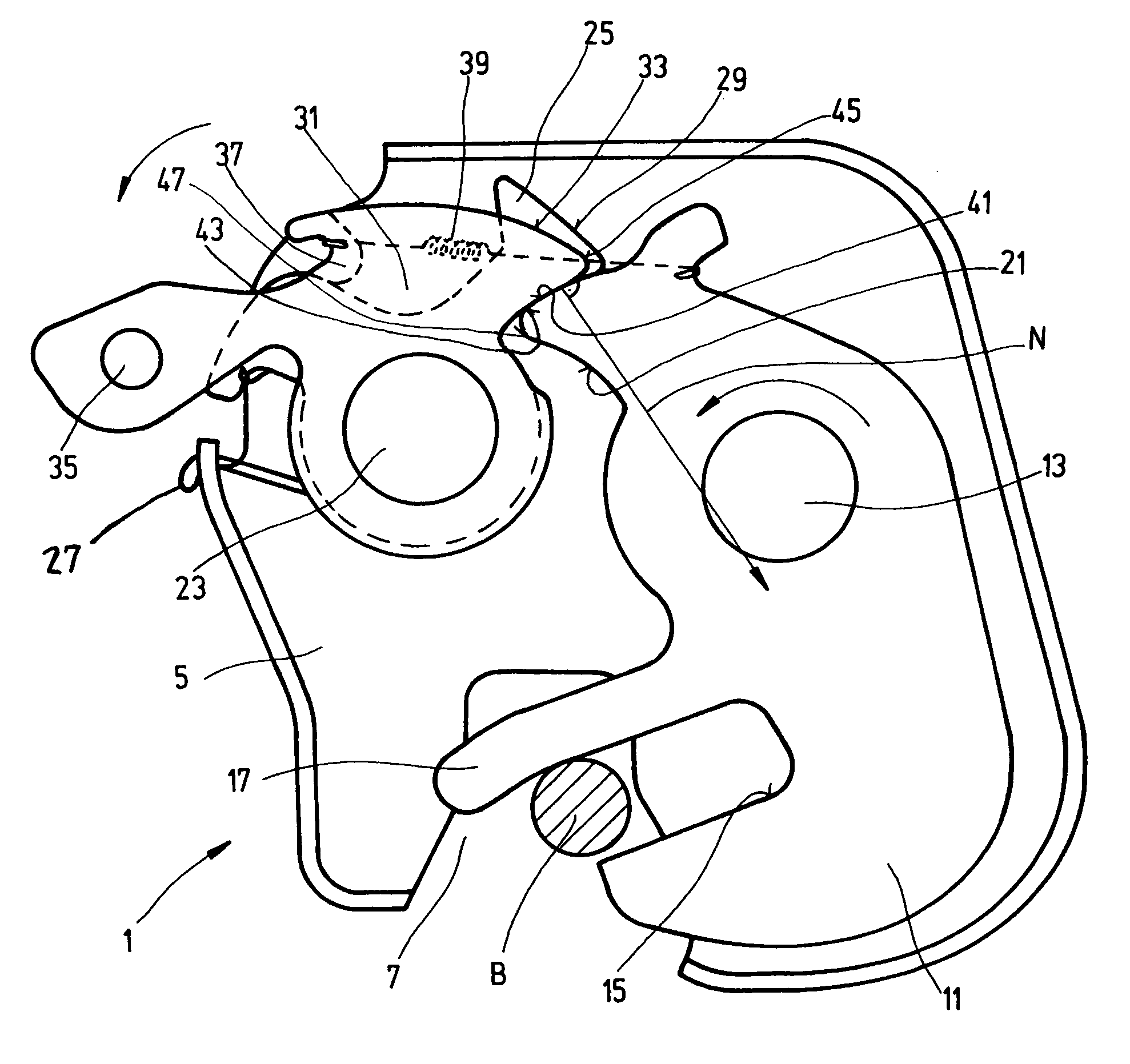
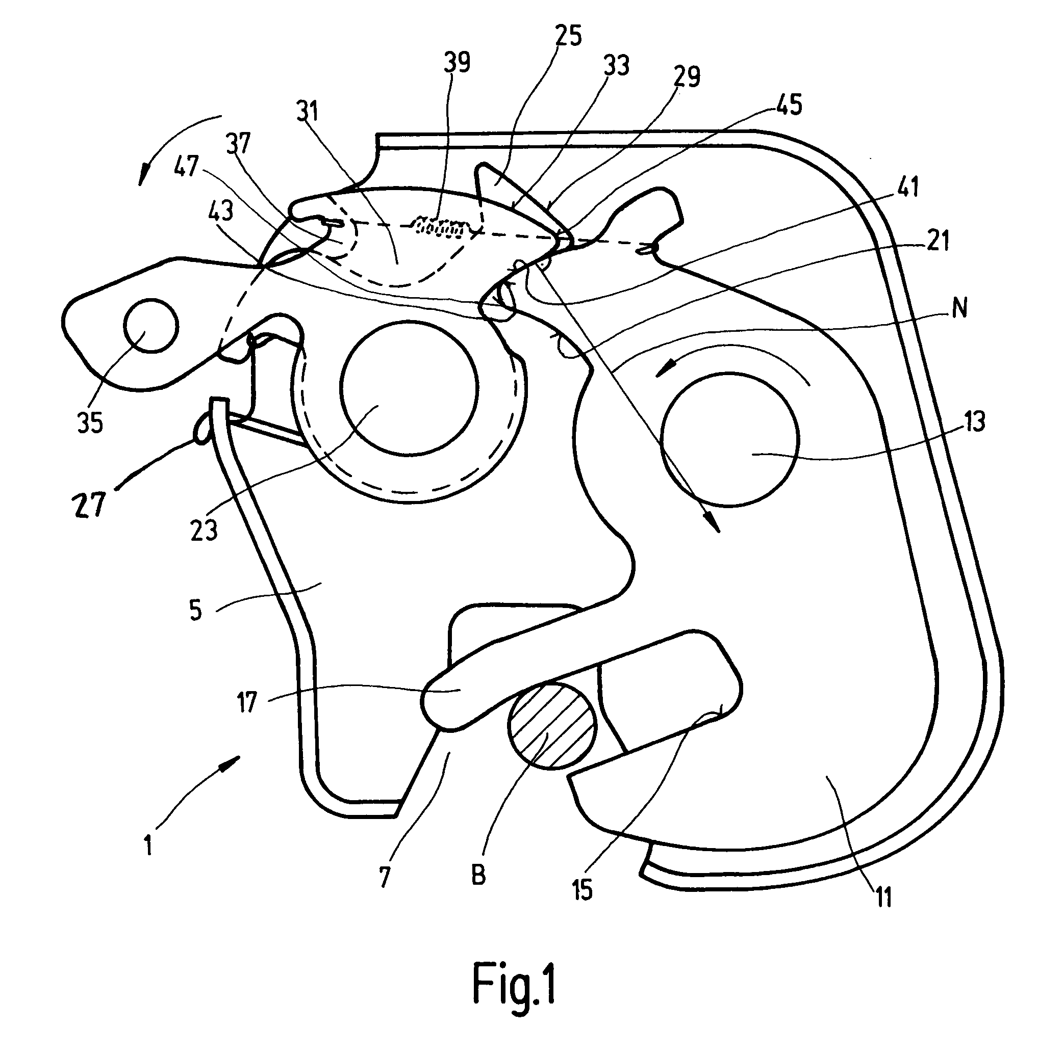
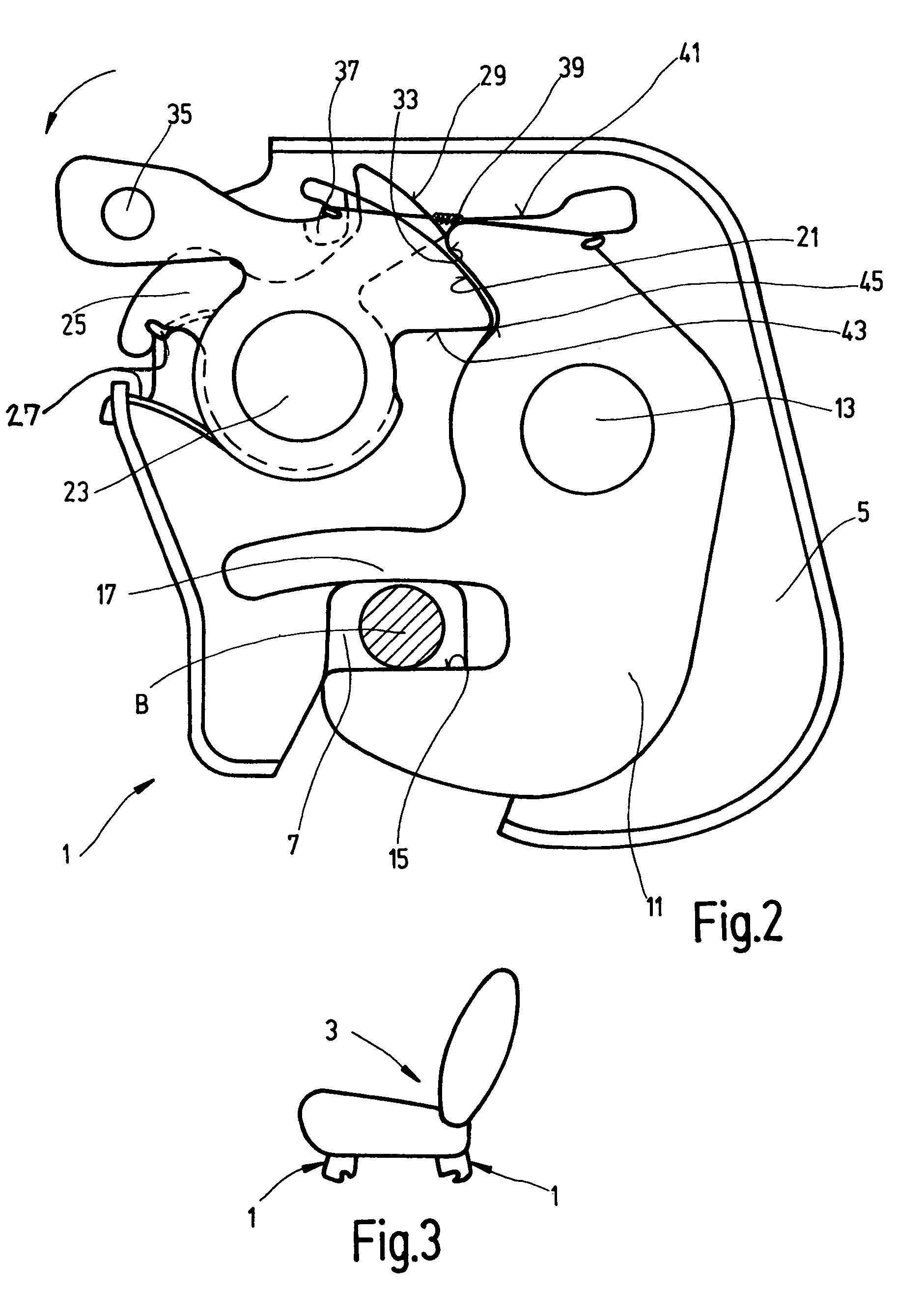
[0014]A locking mechanism 1 is provided for connecting a vehicle seat 3 in a motor vehicle to the floor. The locking mechanism 1 has a housing 5 having a planar base and raised edges. In this Detailed Description section, the base is considered to be vertically oriented and defines the directional information used. The cover which bears against the housing 5 is not illustrated in the drawings. A bolt receptacle 7 is formed in the lower region of the housing 5. The bolt receptacle 7 opens downward and serves to receive a mating element. The mating element can be a bolt B fixed on the vehicle structure, or the mating element can be another mating element. In this case, the width of the bolt receptacle 7 is larger than the diameter of the bolt B in order to compensate for any play. The mating element may also be a section of a bar.

[0015]A pawl 11 is mounted pivotably on a first bearing bolt 13 which is fixedly attached to the housing 5 and protrudes from the housing in the horizontal d...


PUM


Abstract

In the case of a locking mechanism (1) for a vehicle seat, in particular for a motor vehicle seat, having a pivotably mounted pawl (11) for locking to a mating element (B), and having at least one securing element (25, 31) which secures a locked state by interaction with a first functional surface (21) of the pawl (11), and secures an opened state by interaction with a second functional surface (41) of the pawl (11), the securing element (25, 31) exerts an opening moment on the pawl (11) in the opened state.

Description

CROSS-REFERENCE TO RELATED APPLICATION[0001]The present application is a continuation of International Application PCT / EP2004 / 000543, which was filed Jan. 23, 2004. International Application PCT / EP2004 / 000543 is incorporated herein by reference in its entirety.BACKGROUND OF THE INVENTION[0002]The present invention relates to a locking mechanism for a vehicle seat, in particular for a motor vehicle seat, having a pivotably mounted pawl for locking to a mating element, and at least one securing element which secures a locked state by interaction with a functional surface of the pawl.[0003]In the case of a known locking mechanism of the type described immediately above, which is referred to as a rotary latch lock, the securing element is designed as a locking bar which, in the locked state, bears against the first functional surface of the pawl in the self-locking region, whereas a spring keeps the pawl open in the opened state.BRIEF SUMMARY OF SOME ASPECTS OF THE INVENTION[0004]An asp...

Claims


Application Information

Patent Timeline
Patent Type & Authority Patents(United States)
IPC IPC(8): B60N2/015B60N2/90
CPCB60N2/01583B60N2/015B60N2/08
Inventor MULLER, PETERCHRISTOFFEL, THOMASYASAROGLU, KADIRTRAUTMANN, HOLGER
Owner KEIPER SEATING MECHANISMS CO LTD
Why Eureka
Try Eureka