Plow blade with water passageway

Inactive Publication Date: 2006-05-16
VERMEER MFG CO
View PDF12 Cites 0 Cited by
  • Summary
  • Abstract
  • Description
  • Claims
  • Application Information

AI Technical Summary

Benefits of technology

[0008]The present invention relates to a novel design for a plow blade which provides a fluid passage and points of fluid ejection which is produced with basic manufacturing processes allowing efficient production.
[0009]Another aspect of the present invention is a blade construction including a multiple component assembly. This provides the ability to rebuild a blade, replacing a portion of the blade that may be worn.
[0010]In another aspect of the present invention a process of ejecting a specific fluid at specific points along a plow blade the desirable characteristics are maximized, while the volume of ejected fluid is minimized. This method is adaptable in static plowing and vibratory plowing utilities. Lubricating the sides of the blade / chute that come into contact with the ground with fluid has been found to greatly reduce the amount of drag (friction).

Problems solved by technology

This process may be slow and require a large amount of power from the tractor 10 to pull the blade / chute through the ground.
However this requires complicated manufacturing processes, with the result that a wear item, the blade, becomes a relatively expensive component.

Method used


Image

  • Plow blade with water passageway
  • Plow blade with water passageway
  • Plow blade with water passageway

Examples


Embodiment Construction

[0027]Referring now to the drawings, like reference numerals designate identical or corresponding parts throughout the several views. The included drawings reflect the current preferred and alternate embodiments. There are many additional embodiments that may utilize the present invention. The drawings are not meant to include all such possible embodiments.

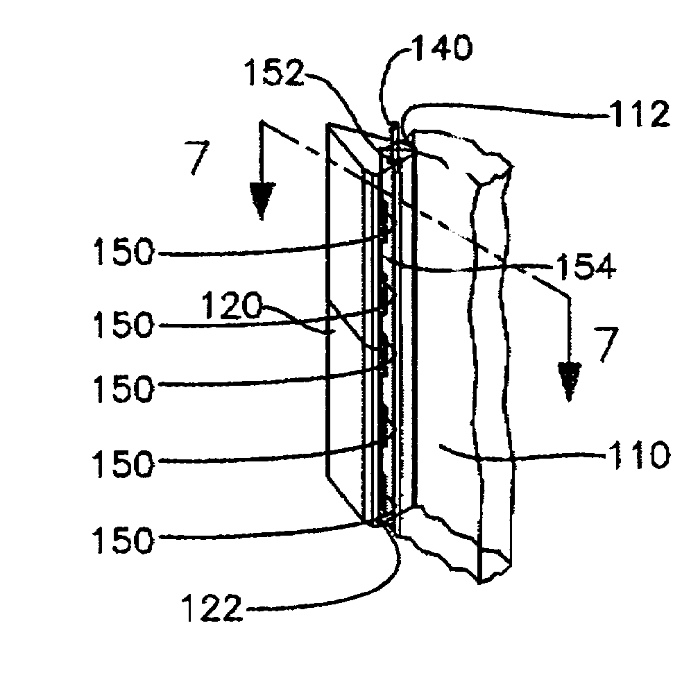
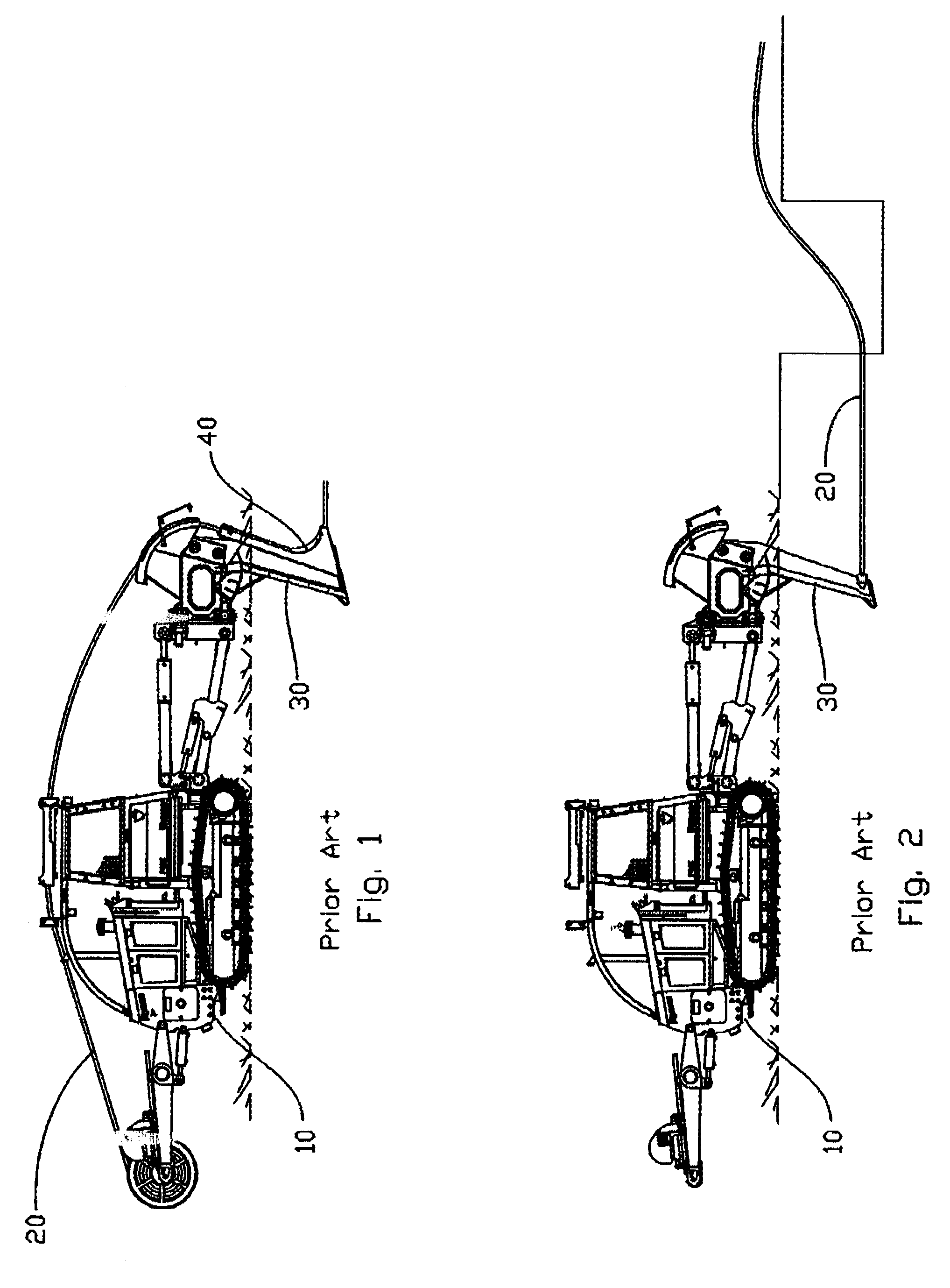
[0028]FIG. 5 illustrates a plow 100 constructed according to the principles of the present invention. Plow 100 consists of blade 110, leading edge sections 120, point 130 and a fluid tube 140. Chute 40 is attached to the rear edge 114 of blade 110, and is constructed to receive and guide utility line 20 from above the ground to the desired depth where it is oriented generally parallel to the ground surface. In other embodiments, the chute may be replaced by a puller adapted to hold a utility line that is being pulled through the ground, similar to the arrangement shown in FIG. 2.

[0029]The blade 110 further includes a front edge 11...


PUM


Abstract

A plow blade having a fluid passageway and points of fluid ejection is produced with basic manufacturing processes allowing for efficient production. The blade construction has a multiple component assembly for providing the ability to rebuild a blade and replacing a portion of the blade that may be worn. In another aspect of the invention a process of ejecting a specific fluid at specific points along a plow blade the desirable characteristics are maximized, while the volume of ejected fluid is minimized. This method is adaptable in static plowing and vibratory plowing utilities since lubricating the sides of the blade / chute that come into contact with the ground with fluid has been found to greatly reduce the amount of drag (friction).

Description

STATEMENT REGARDING FEDERALLY SPONSORED RESEARCH OR DEVELOPMENT[0001]Not ApplicableBACKGROUND OF THE INVENTION[0002]Many types of services are delivered to homes through conduits installed in relatively shallow underground trenches. These include telephone, television, natural gas, electricity, and drainage. These utilities are often installed with a plow. FIG. 1 illustrates an example installation of a utility 20 with a prior art plowing process. A plow 30 is attached to a prime mover, typically a tractor 10. The tractor 10 propels the plow through the ground. The plow 10 is relatively narrow and will split the ground open with a sharpened steel blade. The utility line 20 is introduced into the ground through a chute 40 that is attached to and directly behind the blade. The chute 40 holds the ground open as the utility line 20 is being fed into the desired vertical position and places the utility line 20 into a horizontal position at the desired depth under ground.[0003]An alternat...

Claims


Application Information

Patent Timeline
IPC IPC(8): E02F5/10E02F3/80E02F5/02
CPCE02F3/80E02F5/102E02F5/101
Inventor HOELTING, KEITH A.REEVES, JAMES V.KENKEL, BRIAN N.
Owner VERMEER MFG CO
Why Eureka
Try Eureka