Collision detection and warning system for automobiles

a technology for collision detection and warning systems, applied in vehicular safety arrangments, bumpers, instruments, etc., can solve problems such as difficulty in effectively limiting target areas, difficult to change lanes while driving, and difficult rear looking neck movements for many of today's population, so as to minimize false alarms

Active Publication Date: 2006-05-16
ROBERTS KRISTIE L
View PDF13 Cites 42 Cited by
  • Summary
  • Abstract
  • Description
  • Claims
  • Application Information

AI Technical Summary

Benefits of technology

[0010]Each sensor connects to a circuit board that connects to the control module and the automobile's electrical system. The control module connects to the automobile's electrical system to detect the activation of the left and right turn signals, and an interface electrically connects the control module to the automobile's left and right audio speakers. A mode switch and left and right alarm lights are installed inside the automobile, and each connects to the control module. The four sensor assemblies attach to the sides of the front and rear bumpers, respectively. While the sensors are preferably simple proximity sensors, other sensors could also be used, such as radar, infrared, laser, and ultrasonic sensors, for example. High pass filters may be employed to eliminate signals from low frequency reflections, thus minimizing false positives from stationary objects.
[0012]Therefore, a general object of this invention is to provide a collision detection and warning system for an automobile that can detect objects in the driver's blindspots or other target areas.
[0013]Another object of this invention is to provide a collision detection and warning system for an automobile, as aforesaid, that effectively notifies the driver of impending danger.
[0014]Still another object of this invention is to provide a collision detection and warning system for an automobile, as aforesaid, that minimizes false alarms.
[0017]A still further object of this invention is to provide a collision detection and warning system for an automobile, as aforesaid, that is relatively inexpensive.

Problems solved by technology

It is often difficult to change lanes while driving because the driver's blindspots at the rear and sides of the vehicle cannot be seen with either the rearview or side mirrors effectively.
The rear looking neck movements are difficult for much of today's population, including the elderly, and the movements distract all drivers from looking ahead.
While the technology to achieve collision avoidance, problems with cost and convenience have kept this innovation off most new vehicles and virtually all older vehicles.
Nevertheless, many of these systems have had difficulties effectively limiting the target area to distances that pose a danger to the driver.
These transmitters and receivers act like those mentioned above and poorly limit the target area.

Method used


Image

  • Collision detection and warning system for automobiles
  • Collision detection and warning system for automobiles
  • Collision detection and warning system for automobiles

Examples


Embodiment Construction

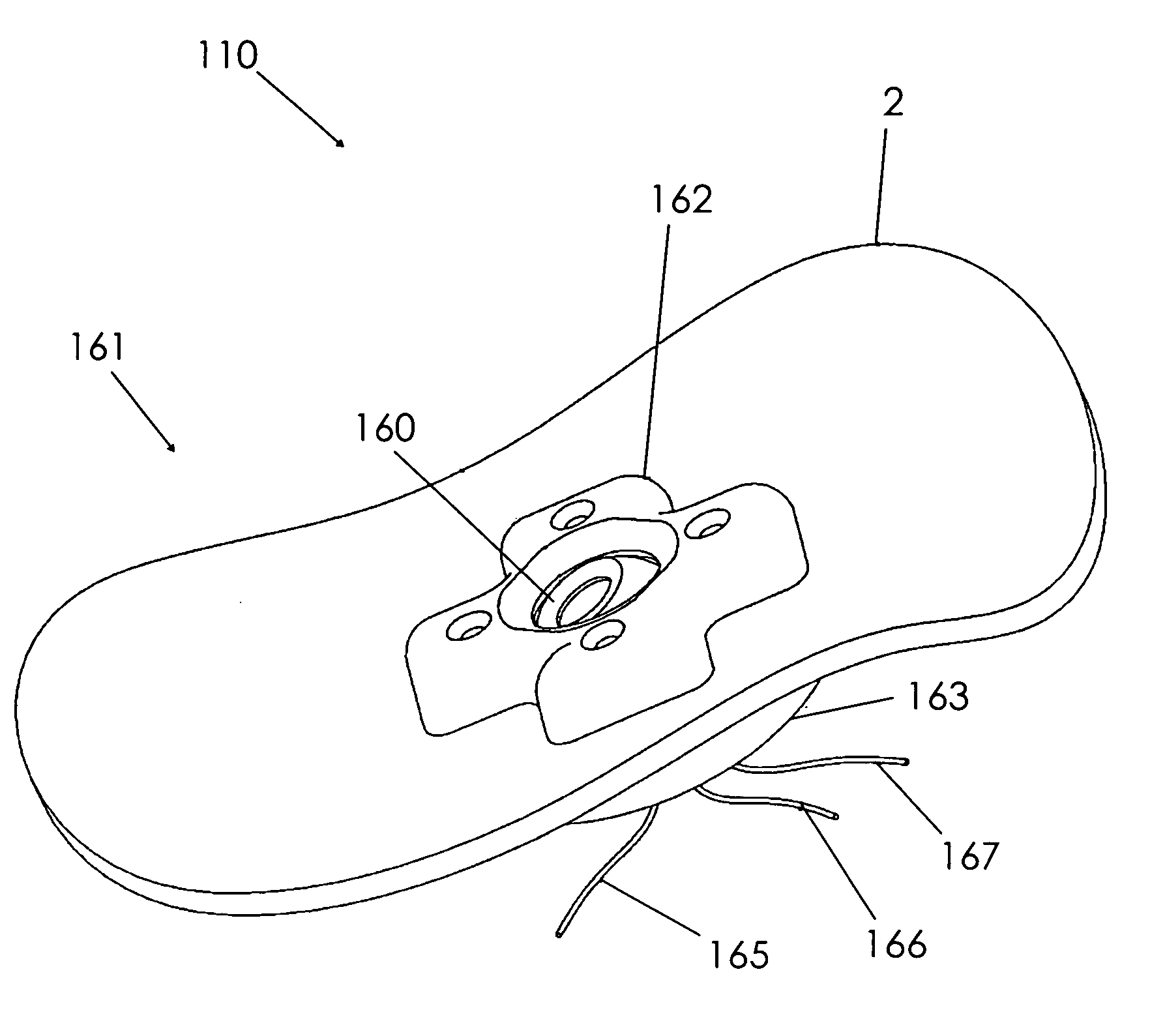
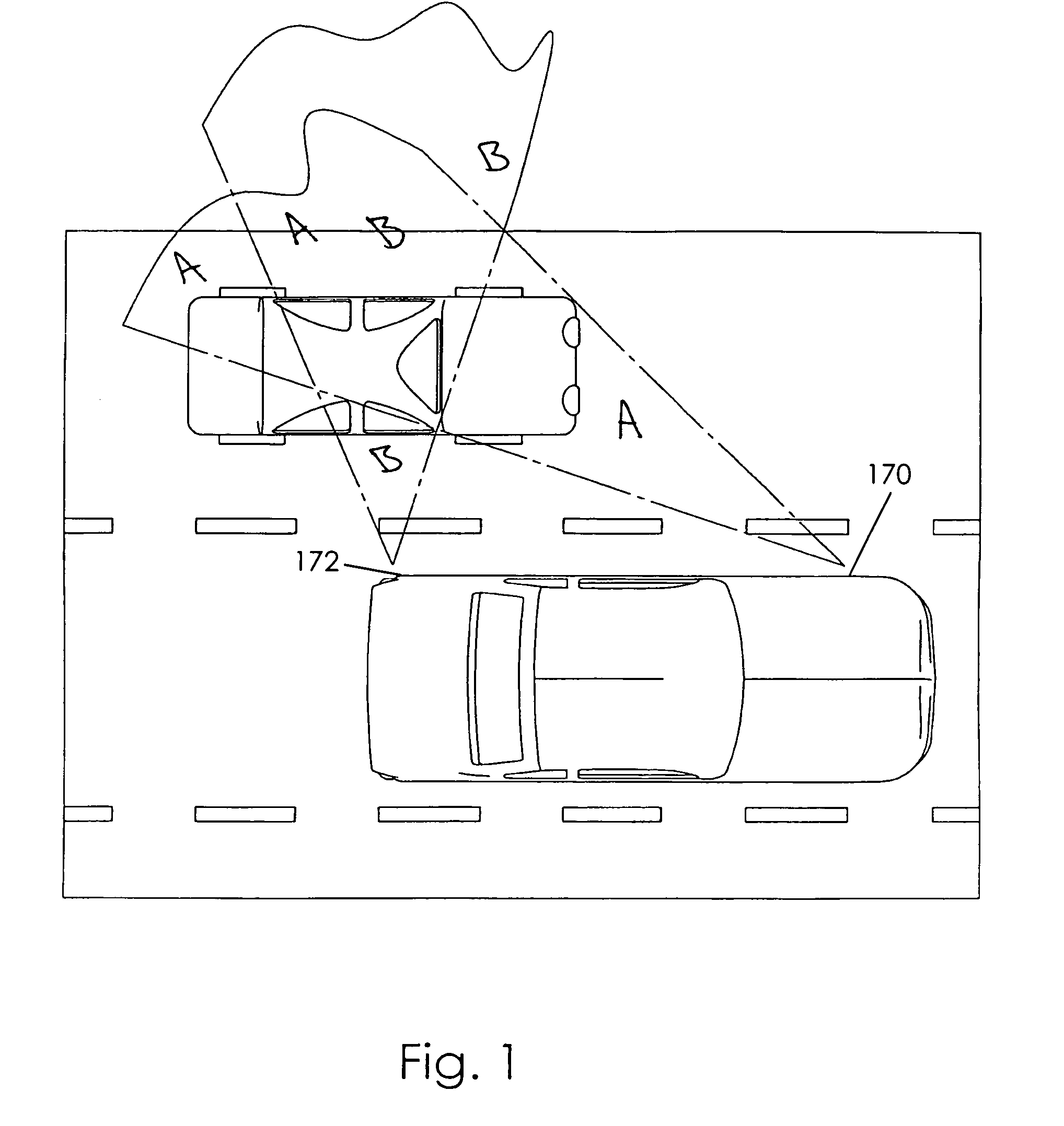
[0026]A collision detection and warning system for an automobile according to the present invention will now be described in detail with reference to FIGS. 1 through 7 of the accompanying drawings. More particularly, a collision detection and warning system 100 according to a now preferred embodiment includes four sensor assemblies 110 and a control module 120. As to be described below in more details, the collision detection and warning system 100 may be electrically connected to a left car audio speaker 132, a right car audio speaker 137, a left automobile turn signal 140, and a right automobile turn signal 145. Accordingly, the system 100 may be retrofitted onto older existing automobiles. In addition, the system 100 may include a left alarm light 130, a right alarm light 135, and a mode switch 150 (FIG. 6).

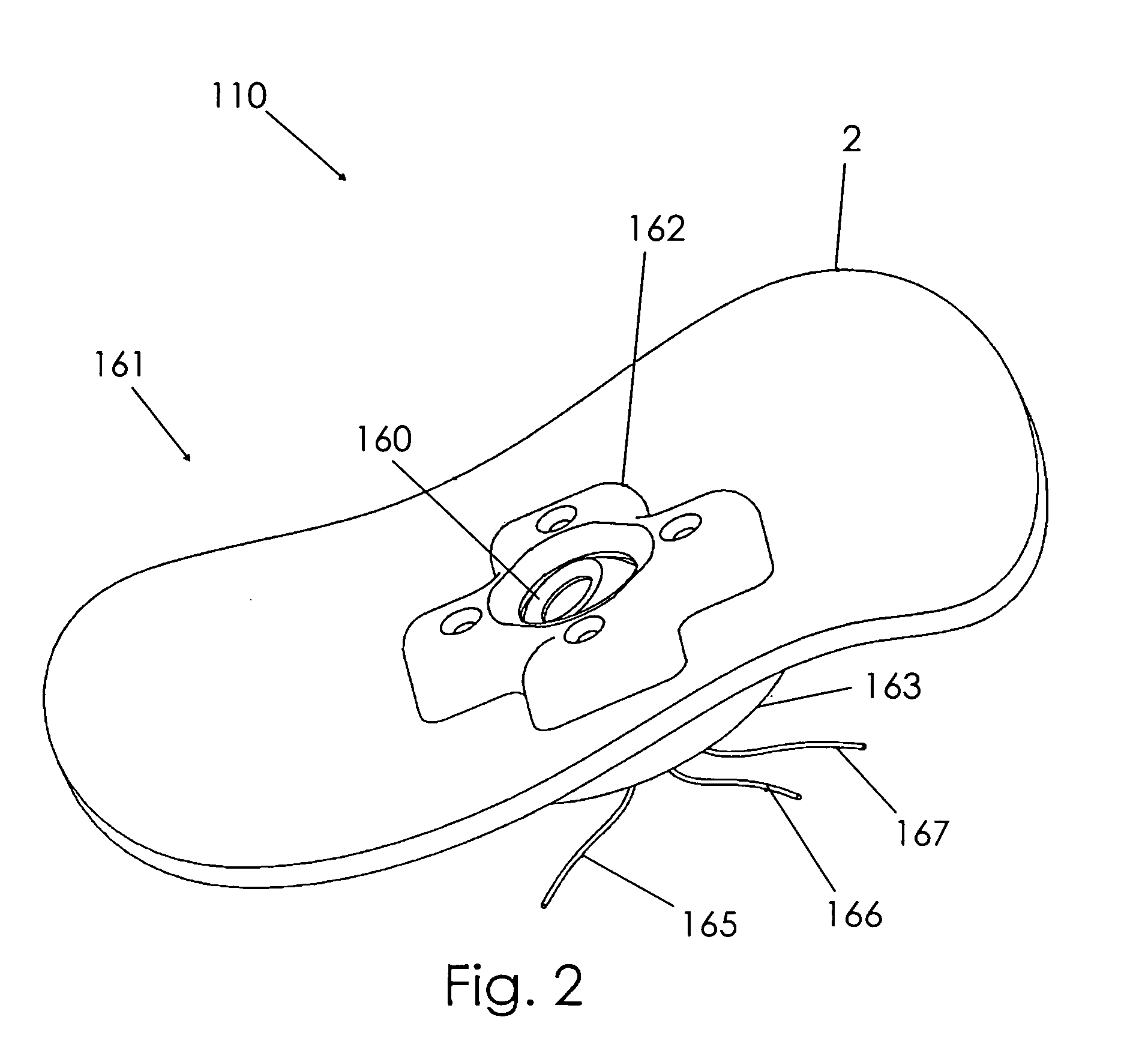
[0027]Each of the four sensor assemblies 110 includes a sensor 160 and a sensor mounting assembly 161. Each sensor mounting assembly 161 includes an outer mounting plate 162, ...


PUM


Abstract

A collision detection and warning system for an automobile having left and right audio speakers and left and right turn signals includes at least four sensors and a control module. The sensors may be mounted on exterior surfaces of the automobile, such as on sides of the front and back bumpers, and are connected to the control module and the automobile's electrical system. The sensors are mounted in mounting assemblies and can be angularly oriented. Each corresponding front and back pair of sensors may detect an obstacle in the driver's “blind spot” when oriented in an appropriate beam splitting arrangement. Upon obstacle detection and actuation of a respective turn signal, the control system sends an alarm tone to the automobile's audio speaker on the side of the car nearest the danger and / or activates a respective alarm light to indicate the direction of danger.

Description

BACKGROUND OF THE INVENTION[0001]This invention relates generally to systems for detecting obstacles and avoiding collisions. In particular, the present invention relates to a collision detection and warning system for an automobile that uses audible alerts to warn a driver of obstacles in the driver's “blindspots” at the rear and sides of the vehicle.[0002]It is often difficult to change lanes while driving because the driver's blindspots at the rear and sides of the vehicle cannot be seen with either the rearview or side mirrors effectively. The rear looking neck movements are difficult for much of today's population, including the elderly, and the movements distract all drivers from looking ahead. A device that would make changing lanes easier and less dangerous would be widely welcomed.[0003]Collision detection systems have been proposed on high-end cars in today's market. While the technology to achieve collision avoidance, problems with cost and convenience have kept this inno...

Claims


Application Information

Patent Timeline
Patent Type & Authority Patents(United States)
IPC IPC(8): B60Q1/00B60Q1/52B60Q5/00B60R19/48
CPCB60Q5/00B60R19/483B60Q9/008
Inventor ROBERTS, KRISTIE L.
Owner ROBERTS KRISTIE L
Why Eureka
Try Eureka